Transcription of For Input/Output - SMC ETech
1 DN1EX250 SCommunication protocolDN1DN1-X102 Note 1)PR1MJ2AS3AS5AS7AS9CA1 AEN1 DeviceNet DeviceNet PROFIBUS DPCC-LinkAS-i (8in/8out 31 Slave Mode, 2 power supply systems)AS-i (4in/4out 31 Slave Mode, 2 power supply systems)AS-i (8in/8out 31 Slave Mode, 1 power supply system)AS-i (4in/4out 31 Slave Mode, 1 power supply system)CANopenEtherNet/IP Note 1) Refer to the SI unit specifications on page 803 for the special order 2) Please consult SMC for the networks other than the ) SY3000/5000/7000, VQC1000/2000/4000/5000, S0700 are not yet UL-compatible. Enclosure IP67 Maximum 32 inputs/32 outputsConnection of sensors with M8/M12 connectors is possibleNote 1) A manifold part number is not specified for the output block and power block. Please consult SMC for the manifold integrated with various field busesConnection of sensors with M8, M12 connectorsOutput equipment connection with M12 connectors (For low watt load)Output equipment connection with M12 connectors (For high watt load)Power supply for output block (For high watt load)Direct mounting, DIN rail mountingMax.
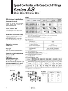
2 32 points actuation1234567SI unitInput blockOutput block Note 1)Output block Note 1)Power block Note 1) End plate assemblyManifold valveHow to Order SI UnitEX250 SeriesFor Input/Output802EX250-SDN1 Note 1)EX250-SDN1-X102 Note 1) This is a specification to transmit the diagnostic information of voltage drop of the valve power supply and input block fuse blowout as an input data to the master. EX250-SDN1 becomes I/O connection time out when the diagnostic information is detected, but not this is a special product, a manifold part number is not specified. Please consult SMC for the manifold integrated 2) Please note that the version is subject to change. Note 3) Each file can be downloaded from SMC website ( ).Note 4) Since EX250-SAS7/9 is compatible with the 1 power supply system, the power supply for units is divided into two: the power supply for sensors and for 5) Since EX250-SAS7/9 is compatible with the 1 power supply system, the power supply must be divided in accordance with the values below.
3 (Refer to page 805 for details.)(EX250-SAS7 Max. 240 mA, EX250-SAS9 Max. 120 mA)Note 6) When the SI unit is mounted to the manifold when shipped, accessories are shipped together with 7) For detailed specifications other than the above, refer to the operation manual that can be downloaded from SMC website ( ).DeviceNet PROFIBUS DPCC-LinkCANopenEtherNet/IP DS-301 DS-401 Release Address k/500 M/3 M/6 M/12 Mbps156 k/625 M/5 M/10 Mbps10 k/20 k/50 k/125 k/250 k/500 k/800 k/1 Mbps10 M/100 MbpsGSD file EDS fileEDS file167 kbpsEDS fileEDS file32/32 Release k/250 k/500 kbps11 to 25 VDC(Supplied byDeviceNet circuit)24 VDC 20% 32/3224 VDC 20%24 VDC 20%64/64(2 stations, remotedevice station)32/3248/3218 V to 30 VDC(Supplied byCANopen circuit)24 VDC 20%48/32 SAS7: 8/8(2 slave units)SAS9: 4/4 SAS3: 8/8(2 slave units)SAS5.
4 4/4 Note 4) to VDC(Supplied byAS-i circuit) to VDC(Supplied byAS-i circuit)EX250-SPR1EX250-SMJ2EX250-SCA1 AEX250-SEN1 EX250-SAS3/5 EX250-SAS7/9 Hold/Clear(Switch setting)ClearHold/Clear(Switch setting)Not providedNot provided (Not required)24 VDC+10%/ 5%SAS7: 100 mA or lessSAS9: 65 mA or lessSAS7: 8 inputsSAS9: 4 inputsNote 5)SAS7: 8 outputsSAS9: 4 outputsNote 5)SAS3: 100 mA or lessSAS5: 65 mA or lessSAS3: 8 inputsSAS5: 4 inputsSAS3: 240 mA or lessSAS5: 120 mA or lessSAS3: 8 outputsSAS5: 4 outputsSAS3: 500 mA or lessSAS5: 250 mA or lessSink/NPN (Positive common)24 VDCIP675 to 45 C 10 to 50 C5 to 45 C35 to 85%RH (With no condensation)500 VAC for 1 min. between whole external terminal and FG10 M or more (500 VDC) between whole external terminal and FGCE marking, UL (CSA)250 gTie-rod 2 A or lessSI Unit SpecificationsModel Communication speedConfiguration file Note 3)Terminating resistorFor unit For sensorsFor valveNumber of inputsSupply voltageSupply currentOutput typeNumber of outputsLoadSupply voltageSupply currentEnclosureOperating temperature rangeOperating humidity rangeWithstand voltageInsulation resistanceApplicable systemProtocolPower supply voltageInternal current consumption (Unit)StandardsWeightAccessory Note 6)CommunicationOutputInputEnvironmentI/O occupation area (Inputs/Outputs)Fail safe24 VDC100 mA or less32 inputs (Based on input block connection) or lessSource/PNP (Negative common)
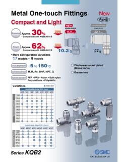
5 Source/PNP (Negative common)32 outputsSolenoid valve with surge voltage suppressor 24 VDC, W or less (SMC)Output blockPower blockVersion Note 2)For Input/Output EX250 Series803EX12 EX140EX180EX260EX250EX600EX500EX510 PCAEX EX250 ADDRESS ERRL RUNx 1x 10 PWPW(V) (DeviceNet )EX250-SMJ2 (CC-Link)EX250-SPR1 (PROFIBUS DP)EX250-SCA1A (CANopen)AS-InterfaceEX250-SAS7/9 (1 power supply system)EX250-SAS3/5 (2 power supply systems) (EtherNet/IP )SI Unit Dimensions/Parts DescriptionPosition indicator LEDS witch protective coverPosition indicator LEDS witch protective coverPosition indicator LEDS witch protective coverPosition indicator LEDS witch protective coverSwitch protective coverPosition indicator LEDP osition indicator LEDS witch protective coverPosition indicator LEDS witch protective coverPosition indicator LEDS witch protective coverLINK IN(M12, 4 pins, plug)LINK OUT(M12, 4 pins, socket)Bus adapterPosition indicator LEDS witch protective coverEX250 terminalGround terminalGround terminalGround terminalGround terminalGround terminalGround terminalCommunication connector(M12, 4 pins, plug)Communication connector(M12, 4 pins, plug)Communication connector(M12, 4 pins, plug)
6 Power supply connector(M12, 4 pins, plug)Communication connector(M12, 4 pins, socket, Type D)Power supply connector(M12, 5 pins, plug)Communication connector(M12, 5 pins, plug)Power supply connector(M12, 5 pins, plug, reverse key)Communication connector(M12, 5 pins, plug)Power supply connector(M12, 5 pins, plug, reverse key)Communication connector(M12, 5 pins, socket, reverse key)Power supply connector(M12, 5 pins, plug)Communication connector(M12, 5 pins, socket, reverse key)Power supply connector(M12, 5 pins, plug)Power supply connector(M12, 5 pins, plug, reverse key)804AS-Interface 8in/8out 31 SlaveMode, 2 power supply systemsAS-Interface 4in/4out 31 SlaveMode, 2 power supply systemsAS-Interface 8in/8out 31 SlaveMode, 1 power supply systemAS-Interface 4in/4out 31 SlaveMode, 1 power supply system123123123123SI unit specificationsEX250-SAS3EX250-SAS5EX250- SAS7EX250-SAS9 When one AS-Interface power supply system is usedEX250-SAS7EX250-SAS9 Supplied from AS-Interface circuit, to VDC Note 1)24 VDCMax.
7 100 mA88 Max. 240 mAMax. 65 mA44 Max. 120 mAPower supply voltageInternal current consumptionNumber of inputsNumber of outputsSupply voltageSupply current Note 2)Note 1) For communication power supply, use a power supply dedicated to AS-Interface. For details, please refer to operation manuals provided by the respective 2) The AS-Interface circuit provides current to the internal parts of the SI unit and all connected there is a limit on the possible supply current to all connected equipment, select the equipment connected to the Input/Output device to stay within the possible supply ) When EX250-SAS9 is used Valve: VQC1100NY 5 (low-wattage type of W) x 4 [W] 24 [V] x 4 [pcs.] = 84 [mA] (4 outputs simultaneously ON)The maximum possible supply current of EX250-SAS9 is 120 mA.
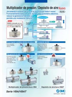
8 Therefore, the possible supply current to the sensor is120 [mA] 84 [mA] = 36 [mA]Use of low-wattage type valves by minimizing the maximum number of simultaneous outputs, and low current consumption sensors (2-wire sensor, etc.) is number of AS-Interface compatible input blocks4 stations2 stations2 stations2 stations1 station1 station4 stations2 stations2 stations2 stations1 station1 stationM12/2 inputsM12/4 inputsM8/4 inputsM12/2 inputsM12/4 inputsM8/4 inputsM12/2 inputsM12/4 inputsM8/4 inputsM12/2 inputsM12/4 inputsM8/4 inputsInput block maximum stationsInput block typeEX250 SeriesPrecautionsBe sure to read this before handling the EX140EX180EX260EX250EX600EX500EX510 PCAEX EX250 Input BlockInput blockOutput blockSI unitPower blockInput blockSI unitOutput blockHow to Order Input BlockEX250 IE1 Block type123M12 connector, 2 inputsM12 connector, 4 inputsM8 connector, 4 inputsInput Block SpecificationsFor options.
9 Refer to pages 808 to type Number of inputsInput device supply voltage Input device supply currentRated input currentDisplayConnector on the input device sideEnclosureOperating temperature rangeOperating humidity rangeWithstand voltageInsulation resistanceNote 1) When the maximum inputs to the SI unit is reached by adding an input block, pay attention not to exceed the supply current for the SI unit 2) When the SI unit is integrated into manifold, its tie-rod is also incorporated at the time of 3) For detailed specifications other than the above, refer to the operation manual that can be downloaded from SMC website ( ).ModelEX250-IE1 PNP/NPN sensor input (switched using a switch)24 VDCMax. 30 mA/point Note 1)Approx. 8 mAGreen LED (Lights up when the power supply for the SI unit input is applied),Yellow LED (Lights up when the input signal is turned on.
10 2 inputsM12 connector (4 pins, plug or 5 pins, plug)M8 connector (3 pins, plug)4 inputsInput EnvironmentStandardsWeightAccessory Note 2)EX250-IE2EX250-IE3IP67 10 to 50 C35 to 85%RH (with no condensation)500 VAC for 1 min. between whole external terminal and FG10 M or more (500 VDC) between whole external terminal and FGCE marking, UL (CSA)90 gTie-rod 2 Series806EX250-IE1, VPNPSWRRNPNRR24 VFuse( A)qrewtqrewtInternal circuittwqrerqeInput Block Dimensions/Parts DescriptionFuse Note)NPN/PNP convertion switchPosition indicator LEDP osition indicator LEDC onnector s pin assignment for theinput device connection(M12, 5 pins, socket)Circuit diagram: EX250-IE1 RRRRFE0 VRPNPSWRRNPNR24 VFuse( A)qrewtqrewtInternal circuitCircuit diagram: EX250-IE2 Circuit diagram: EX250-IE3 RRRR0 VRPNPSWRRNPNR24 VFuse( A)qreqreqreqreInternal circuitEX250-IE3 Fuse Note)NPN/PNP convertion switchPosition indicator LEDNote) Fuse for overcurrent protection If addressing the possible cause of a problem, even when the fuse is blown, it can be reinstated by replacing with a fuse as shown in options, page 809 Connector s pin assignment for theinput device connection(M8, 3 pins, socket)For Input/Output EX250 for input device connection(M12, 5 pins, socket)Connector for input device connection(M8, 3 pins, socket)807EX12 EX140EX180EX260EX250EX600EX500EX510 PCAEX EX250 OptionsExample of connections Connection example of the SI unit compliant with EtherNet/IP Connection example of the SI unit compliant with DeviceNet u Power block P.