Transcription of Frequency Distribution Design Basic Module - …
1 Frequency Distribution Design Basic Module Document version One of the main components of the Frequency Distribution is the Distribution Amplifier. In order to Design a circuit suitable for this function, you must first of all, locate the main features that are non-negotiable from a technical point of view. Some features may be: - AC and DC backup power supply - High reverse isolation - High channel to channel isolation - Low Residual Phase Noise - High power level capability - Low cost We can then investigate the requirements for the achievement of each of these elements. AC and DC power supply The power sources must be very flexible, for the supposed to be AC suitable for countries that use 60 Hz 115 Volts than for those are using 50 Hz 230 Volts.
2 For external DC backup power source, the range it might be 24-28 Volts. Now we have to convert these input voltages in those necessary to power the internal circuitry, taking into account that one of the main requirements is to have internal voltages with very low residual noise to avoid the modulation of the Frequency standard signals flow in the Distribution amplifier. To simplify the project will be well Design an amplifier circuit that uses a single supply voltage and that is few volts below the minimum of the DC backup voltage to be able to use a low noise linear voltage regulators with. Starting from a minimum input of 24V, a voltage of 18 Volts is a good compromise which combines minimum 6 V dropout and an quite high voltage to the output stage for an high power level handling.
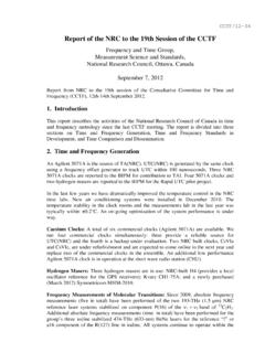
3 The power supply could be so organized: 90-240 Volts 50-60 HzSwitching Power supplyNoise FilterP ch. MosfetAC-DC SwitchComparatorLinearReg.+18 VDC INPUTAC INPUT The switching power supply ensures high efficency and low operating temperatures. A balanced passive filter can reduce up to 60% of the output spikes level. A fast Power source switch, controlled by a voltage comparator, enables the external DC path when the AC input fail. This particular power management permit a low operating voltage of the AC power supply and consequently a low thermal dissipation of the linear 18 Volts regulator. The linear regulator cleans again from the noise both the external AC and DC power sources.
4 High reverse isolation The Distribution amplifier will be composed of N amplifier/separators equal between them that will have a high input impedance to be put in parallel and form a single common input point and several independent outputs with a 50 Ohm impedance. Further attention will be to isolate the ground output connection from the low frequencies in order to avoid current loops. This happen in complex configurations, they can introduce interferences in signals to be distributed. Reverse isolation is one of the most important features that must have an amplifier. A great isolation save the source signal from disturbances that may occur when happen an output short-circuit, impedance mismatch or interference source connected to the output of the Distribution amplifier.
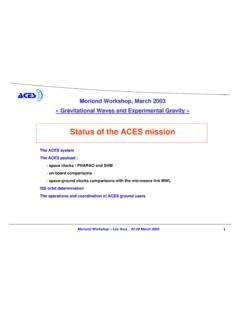
5 Some Distribution Amplifier use the Operational Amplifiers because the low cost circuit and only few components needed but this solution has a very low reverse isolation. They are done for commercial video Distribution use, is a very low-cost remedy with low performances. A good Amplifier-Separator configuration is to use two different aplifier stages, a Totem Pole guarantees an excellent reverse isolation followed by a current amplifier that fits the relative high output impedance of the first stage with the output impedance required of 50 Ohm. INPUTOUTPUTAMPLIFIEROUTPUTREVERSE ISOLATIONTest SourceMeter Reverse isolation measurement setup High channel to channel isolation Another important parameter is the separation between channels that guarantees isolation between outputs.
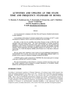
6 In case of a short-circuit of an output you must avoid the other outputs are involved in signal variations, then the greater is the separation between outputs, smaller will be involved other channels. The channel to channel separation is tipically lower than the reverse isolation. To better understand you can see below an example of calculating where the reverse isolation value have to be added algebrically to the direct gain of the second amplifier. Inputclosed on 50 OhmAMPLIFIERGain 3dBChannel to Channel IsolationTest SourceMeterAMPLIFIERGain 3dBReverse isol -100dBGain +3dBChannel toChannel isolation97dB There may be other factors which influence the separation between channels, such as the capacitive couplings due to the proximity of the output connectors and the same components of the adiacent amplifiers, especially if not shielded between them.
7 A smd low profile realization, help to limit the coupling between the channels. Low Residual or Additive Phase noise In signal processing phase noise is the Frequency domain representation of rapid, short-term, random fluctuations in the phase of a waveform, caused by time domain instabilities. All real oscillators and the related components like a Distribution amplifier have phase and aplitide modulated noise components. The phase noise components spread the power of a signal to adjacent frequencies, resulting in noise sidebands. When we talk of this added noise it is referred to as Additive or Residual Phase Noise, a noise component that is added to the signal that passes through to the quadrupole or is generated by an oscillator.
8 The Residual or Additive Phase noise in oscillator or amplifiers comes from two different sources; additive voltage fluctuations and direct parameter modulation. Additive noise is generally caused by thermally-generated voltage fluctuations that are added to the carrier signal and result in phase and amplitude fluctuations. This type of noise shows up as the nise floor at large Frequency offsets from the carrier(short Tau values) and is flat (white) phase noise. The second type is modulation noise. The most well known si flicker (1/f) noise. This is caused by direct phase or Frequency fluctuations in the resonant device or by phase fluctuations in other electronic components.
9 A Distribution amplifier must be able to handle an input signal with the addition of minimum phase noise. Only a careful Design and selected components can ensure a low Residual Phase Noise. High power level capability Making of investigations about the market concerning time and Frequency equipment, you can locate more parameters used in connections between equipment. One of these parameters is for a standard power level that tipically is +13dBm. Taking this figure, we have to consider a project that is able to have an operating margin greater than this value of approximately 3 or 4dBm.
10 This focus is essential to avoid saturating the amplifier and produce harmonic distortion that would compromise the integrity of the signal. Low Cost A typical Distribution amplifier is configured to have 12 outputs. This involves a large number of components, therefore a production and selling cost high. Is therefore very important to find the right balance between performance, reliability and a moderate cost. This objective have to be treated during both the project and engineering phases . The proposed solution uses components very common then, beyond that of easy availability, also cheap.