Transcription of FreudTools Router Bit Feed and Speed for CNC
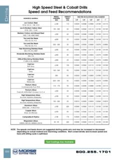
1 Get the most out of your Freud bits by routing at ideal feed rates and speeds Read all safety warnings and all instructions provided with the Router bit and in the machine manual. Failure to follow the warnings and instructions may result in electric shock, fire and/or serious injury. To reduce the risk of injury, always check to ensure the rated Speed of the Router bit is higher than or equal to the maximum Speed marked on the CNC machine. Router bits running faster than their RATED Speed can break and fly apart. To get the longest life and the best cut quality from your bits, you need to match the feed rate of your CNC and the Speed (RPM) of your Router spindle to the material you are routing and the bit you are using. Routing at the best combination of feed Rate and RPM is critical to quality of your work and the durability of your Freud Router bits. 1) There is no hard-and-fast rule for precisely what feed Rate and Speed will be best for your project and your CNC.
2 The formulas and chip load values in the chart below provide a good range of feeds and speeds for you to start with, but you should always make some test cuts with your bits in scrap material to be sure you get the best possible results. As you make your test cuts, observe the following best practices: a. Always consult your machine s operation manual for bit capacities and recommended feed rates. b. Always start with shallow passes in your test cuts to reduce strain on your bit and your CNC. c. You should start your tests with the lower feed rates yielded by our formulas to reduce the chance of bit breakage. (Freud s chart contains recommended starting points, and does not warranty against tool breakage) d. Carbide tipped bits should not be used to drill directly into the work piece. 2) Second, you need to consider the design of the bit you are using: - Number of Flutes, or cutting edges: More flutes on a bit may produce a finer finish on the workpiece than a bit with fewer cutting edges, but only if your feed and Speed are set correctly.
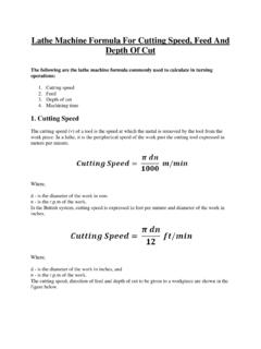
3 Our formulas include a variable where you will enter the number of flutes of your bit so you can consider this factor. - Cutting Depth: This is the depth that will be routed in a single pass. Our feed and Speed recommendations are based on a depth of cut that is no greater than the bit diameter, such as a diameter bit routing a deep pass. If you plan to rout deeper than this in a single pass, you must reduce your feed rate. If Cut Depth is 2X the bit diameter, reduce the Chip Load by at least 25% If Cut Depth is 3X the bit diameter, reduce the Chip Load by at least 50% Please see example #3 for more information. Never exceed the recommended cutting depth listed on the Router bit package or the bit s safety instructions! 3) Next, use the formulas below to calculate starting points for your test cuts. You will notice that our formulas use values called Chip Loads to determine the feed rates and speeds. The Chip Load is the size (thickness) of the chip produced as your bit cuts.
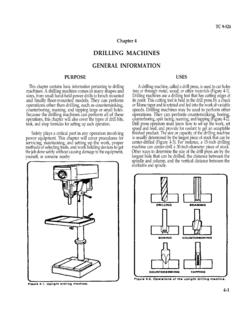
4 Why does this matter? If your chip is very small, or just sawdust, then it will not carry enough heat away from the edge of the bit. Excessive heat will prematurely dull the edge of the solid carbide or carbide tipped Router bit. If the chip is too large, it will leave a rough surface or edge on your work piece. Here are the formulas to make feed and Speed calculations using these values: Chip Load = feed Rate (RPM x number of flutes) feed Rate = RPM x number of flutes x chip load RPM = feed Rate (number of flutes x chip load) Note: feed Rate will be expressed in Inches per Minute Here are some examples: 1. You decide to test a Chip Load of .019" for your cut. Your CNC spins the bit at 18,000 RPM, and the bit has 2 flutes (cutting edges). To determine the feed rate: feed Rate = 18,000 x 2 x .019". Therefore, your feed Rate should be 684 inches per minute. 2. You already know that you want to use a feed Rate of 684 inches per minute, and a Speed of 18,000 RPM.
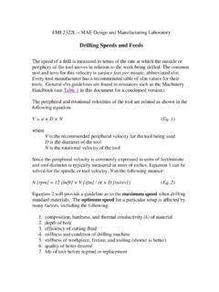
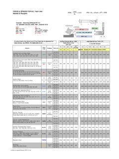
5 Your bit has 2 flutes. To verify that the chip load will be within the recommended range: Chip Load = 684 inches per minute (18,000 RPM x 2 flutes). Therefore, your Chip Load is .019". CHIP LOADS FOR FREUD SOLID CARBIDE Router BITS ONLY: Recommended* Chip Loads, based on cut depth equal to bit diameter:Tool DiameterMDF/ Particle Boa rdLaminated Particle Boa rdHardwoodSoftwoodAcrylics/ Soft Pla sticSolid Surface/ Hard PlasticPlywoodAluminum1/8".004" "003"-006".002" ".004" ".003" ".002" ".003" ".003" "1/4".013" ".010" ".008" ".010" ".006" ".005" ".006".009".005" "3/8".018" ".014" ".014" ".016" ".010" ".008" ".015" ".006"-,.008"1/2".023" ".022" ".018" ".020" ".012" ".010" ".018" ".008" "RECOMMENDED* CHIP LOADS FOR FREUD CARBIDE TIPPED STRAIGHT AND PROFILE BITS ONLY: Tool DiameterMDF/ Particle Boa rdLaminated Particle Boa rdHardwoodSoftwoodAcrylics/ Soft Pla sticSolid Surface/ Hard PlasticPlywoodAluminum1/8".002" "003"-006".002" ".003" "003"-006".
6 002" "003"-005"N/A1/4".004" ".006" ".005" ".006" ".006" ".004" ".005" "N/A3/8".005" ".007" ". ".008" ".007" ".005" ".006" "N/A1/2".006" "008" ".008" ".008" "008" ".006" ".007" "N/A5/8".006" ".009" ".008" ".009" ".009" ".006" ".008" "N/A3/4".007" ".010" ".009" ".010" ".010" ".007" ".009" "N/A*This chart is a recommended starting point and does not warranty against tool your machine's owners manual for bit capacities and recommended feed rates. Always make test cuts with shallow passes in scrap material to verify your feed & Speed rates and cutting depths. Start your tests with the lower feed rates yielded by our tipped bits should not be used to drill directly into the work piece.*This chart is a recommended starting point and does not warranty against tool your machine's owners manual for bit capacities and recommended feed rates. Always make test cuts with shallow passes in scrap material to verify your feed & Speed rates and cutting depths.
7 Start your tests with the lower feed rates yielded by our formulas. 3. Adjusting feed and Speed for Bit Diameter: The chip loads in the table above are based a cutting depth that is equal to or less than the bit diameter. For deeper cuts, you need to adjust the Chip Load as follows: If Cut Depth is 2X the bit diameter, reduce the Chip Load by at least 25% If Cut Depth is 3X the bit diameter, reduce the Chip Load by at least 50% For example, let s say that our chart calls for a chip load of .019 for your application, BUT you decide to use a diameter bit routing 1 deep. Since your cutting depth is now 2X the bit diameter, you must reduce the chip load as follows: .019 x .75 = .014 Chip Load.