Transcription of FUEL LEVEL SENDER - 3 TERMINAL WATER ... - …
1 FUEL LEVEL SENDER - 3 TERMINALWATER LEVEL SENDER - 3 TERMINALM odel # GSFLCAll Lengths Model # GSWLCAll LengthsInstallation InstructionsFUEL SENDING the depth of your tank from the outside top to the tank a tubing cutter cut the outside tube approximately 1/2 inch shorter than the measured depth. (On a V-shaped tank, it is recommended to cut the tube 1" shorter than the tank depth). Be careful not to damage the center are placed on the center tube to prevent it from touching the outside tube. Slide the exposed insulators on the center tube up until they are just inside the outside wire cutters, cut off the center tube flush with the outside tube. Be sure the two tubes are not touching. The gauge will stay pegged above the Full mark when the ignition is turnedon if they are " Senders can only be cut to 6" and 24" Senders can only be cut to 13"36" Senders can only be cut to 25" and 48" Senders can only be cut to 37" unit is calibrated at the factory prior to shipment - recalibration will be required if you have to cut your unit; otherwise a minor adjustment of the FULL screw is all that may be required if you use your own sure the unit is dry before you attempt to calibrate.
2 Residual liquid left inside the tube will give an erroneous reading and affect the calibration. If your unit has been immersed in liquid,let it dry for two hours before you calibrate. The EMPTY and FULL adjustment screws are located on top of the unit. A small phillips screwdriver is required to make the NOT install sensor in tank at this :DISCONNECT THE BATTERYBEFORE MAKING ANYELECTRICAL CONNECTIONS! the wiring connection as shown on the wiring : 12 volt power is required to SENDER & SENDER out of tank and all wires properly connected you can start Turn the FULL and EMPTY screws to the full clockwise position. Do not force the Slowly turn the empty screw counter clockwise until the needle on the gauge just stops moving downward (the needle should be just below the EMPTY mark).715 Center Street * Grayslake, IL 60030 * Office: (847) 752-2700 * Fax: (847) 752-2415web site: * email: 1 of 4C. Now turn the empty screw clockwise to make sure the needle starts moving upscale immediately.
3 THIS IS YOUR EMPTY Now install the SENDER in the tank and FILL TANK WITH FUEL. For best results the tank needs to be full and the boat should be in the WATER . The attitude of the boat will change from boat sitting on the trailer compared to floating in the Turn the "FULL" screw counter clockwise until the needle is on the FULL mark not past it. Do not "PEG" the gaugeF. To check calibration remove SENDER from tank and allow to dry - once dry gauge should read at completes calibration. Do not make anymore InstallationIf you had to cut your sending unit then the EMPTY adjustment must be made prior to calibration instructions).Place the gasket on the sending unit. Align the holes and apply a sealer such as Permatex on thegasket. Put a small amount of sealant in the mounting holes and insert the mounting screws withflat washers and lock washers. Place the sending unit in the tank. Note the holes are notsymmetrical, rotate until all the holes line up, then tighten down the mounting :It is recommended that number 16 AWG wire and crimp eyelet type terminals withinsulated shanks be used to wire the sending units to avoid the possibility of shorting the all wire terminations with nuts and lock !
4 DISCONNECT THE BATTERY BEFORE MAKING ANY a wire from the SEND TERMINAL on the unit to the SEND TERMINAL in the a wire from the POS TERMINAL on the unit to the POS or IGN TERMINAL on the meter orto the 12 volt (24 or 32 volt if specified) electrical system at some point after the ignition a wire from the NEG TERMINAL on the unit to the NEG or GND TERMINAL on the meter and to the boat ground (Neg. 12 volt TERMINAL ). completes the installation. Put a generous coating of sealant over the wires terminals and the adjustment the battery and turn on the ignition switch, the meter will go to the FULL mark then drop back to indicate the correct fuel a wire from the SEND TERMINAL of each unit to each side of the Dual Tank a wire from the center TERMINAL of switch to the SEND TERMINAL on the POS and NEG terminals as instructed for the single tank. Put a generous coating ofsealant over the wire terminals and the adjustment the battery and turn on the ignition switch, the needle on the meter will go to the FULL mark, then drop back to indicate the correct fuel the Dual Tank Switch to read the other tank.
5 The meter pointer will be indicatingslightly below your actual tank LEVEL . Turn off the ignition switch, then turn on. The needle will go tothe FULL mark then drop back to indicate the correct fuel 2 of 4 TROUBLE SHOOTING HINTSSYMPTOMM eter pointer stays above FULL mark when the Ignition switch is turned ) Full tank of ) WATER in fuel ) SEND and NEG wires reversed on Sending ) Meter not grounded ) SEND wire is touching NEG TERMINAL or wiring6) Center rod on fuel units touching the outside ) Unit not tank only: End of tube not sealed TANK WATER tank units are not interchangeable with the fuel tube has two wires; an insulated (sensor) wire through its center and a bare (ground) wire along the outside. The tube is to hold the wire in IS IMPORTANT THAT THE END OF THE INSULATED (SENSOR) WIRE BE SEALED TO PREVENT THE CENTER CONDUCTOR FROM TOUCHING THE WATER . THE METER WILL STAY PEGGED ABOVE THE FULL MARK IF THE END OF THE WIRE IS NOTSEALED bare wire is the ground wire.
6 If your tank is not grounded or is constructed of plastic thenthis wire must be touching the WATER for the unit to work the bare wire which is looped on itself at the bottom of the tube. Remove the tube from the holder: the tube is press fit on the holder and can be removed by pulling and twistingslightly. Do not over twist or you will break the bare wire. the depth of your tank. Cut the tube approximately 1/2 inch shorter than the depth measured. Drill another hole in the bottom to route the bare wire through after the Insulated wire 1/2 inch shorter than the measured is recommended that Dow Corning 100% Silicone Rubber "Gasket In A Tube" be used to seal the end of the insulated wire after it is cut to length. Put a one inch piece of Heat Shrink over the sealant to reinforce the seal. Allow the sealant to dry for four hours before attempting to immerse in the tube on the holder. Route the bare along wire along the outside and through the new hole on the bottom.
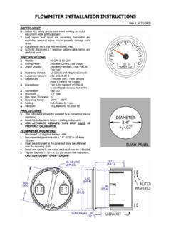
7 Loop it back on steps 5 thru 9 calibrating :Fuel senders must be calibrated in fuel and WATER senders must be calibrated in 3 of 4 Livorsi Marine CenterStGrayslake IL 60030Ph:847-752-2700 DIAGRAMSTANDARD 5-HOLE BOLT PATTERNACTUAL SIZE IF CIRCLE MEASURES 2 5/8 5 each#10 screw holeson diameter circle(use 1 stainless screws) tankopening80deg68deg72deg72deg68 degDOWN If SidemountGASKETHEAD DIAM= SCREWHT= @ 1/2 @ 1/4 @ 1/2 @ 1/4 @ 1/2 @ 3/4 Page 4 of 4 LENGTHAS REQ DHEAD