Transcription of Fundamentals of Vibration Measurement and …
1 Phone: Fax: Email: Website: +61 (0) 402 731 563 +61 (8) 9457 8642 Fundamentals of Vibration Measurement and analysis Explained Thanks to Peter Brown for this article. 1. Introduction: The advent of the microprocessor has enormously advanced the process of Vibration data acquisition and analysis in recent years. Measurement tasks that took hours only two decades ago can now be completed in minutes and better decisions made because of better data presentation. However, the basic processes of Measurement and analysis have remained essentially unchanged, just like the machines from which the Vibration is measured. The results of the Measurement and data analysis need to be compared with known standards or guidelines and decisions made as to whether the machine is acceptable for service or maintenance should be planned.
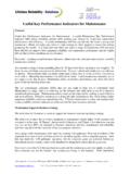
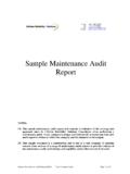
2 Increasingly these processes are being handled electronically but we are still a long way from replacing the fundamental knowledge and experience of the Vibration analyst. In this article we will review the basic principles of Vibration Measurement and analysis in order to lay the foundation for capable fault diagnosis to be considered later. 2. Fundamentals of Vibration : A simple machine may be represented as in the diagram below having mass, stiffness and damping. If we take this simple, single-degree-of-freedom model and excite it with a sinusoidal force F(t) then the distribution of forces generated by the resulting dynamic displacement x may be determined by the following equation: )(tFkxxcxm Mass-Inertia Damping-Velocity Stiffness-Displacement Acceleration Velocity Displacement The above diagram can be easily related to the typical independent front suspension of a vehicle.
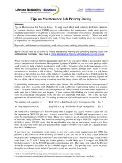
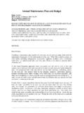
3 Consider how the displacement x might change with changes in spring stiffness, shock-absorber damping rate and mass of the wheel and suspension system. Phone: Fax: Email: Website: +61 (0) 402 731 563 +61 (8) 9457 8642 2 The graph below shows the typical relationship between displacement, velocity and acceleration for a sinusoidal (single frequency) Vibration . Note that displacement amplitudes decrease to very small amplitudes above about 100 Hz. For that reason, seismic displacement measurements are rarely used for machine condition monitoring. They are more useful for monitoring structural Vibration . Velocity tends to have a reasonably uniform response over a wide range of machine frequencies and for that reason it is the universal measure of evaluation of machine integrity in relation to balance, tightness, alignment and the like.
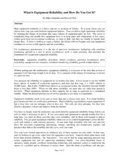
4 Acceleration increases relative amplitude with increasing frequency and is therefore the logical choice for monitoring those components that generate high frequency Vibration such as bearings, gearing and blade-passing (as in screw compressors). As was mentioned in Session 3, the high frequency sensitivity of accelerometers is used to provide measures of rolling-element bearing condition and all these measures are in acceleration units. 3. Measuring Vibration . The diagram on the opposite page shows diagrammatically the general arrangement for Vibration measurements using an Overall Vibration Values. The output of the accelerometer is an AC waveform that exactly reproduces the Vibration acceleration.
5 This waveform might be useful for an experienced Vibration analyst to use for fault diagnosis but for most situations it is not appropriate or even necessary. It is much more useful to measure the total power of the waveform and express it as a DC value. We call this the OVERALL VALUE OF THE Vibration . Phone: Fax: Email: Website: +61 (0) 402 731 563 +61 (8) 9457 8642 3 Phone: Fax: Email: Website: +61 (0) 402 731 563 +61 (8) 9457 8642 4 To get this overall value we need to do an RMS (Root Mean Square) calculation on the AC signal. Older style Vibration meters were able to calculate RMS values using simple analogue circuits.
6 Modern machinery analysers do the same thing via a more complex process of signal digitisation. Overall Vibration measurements, usually expressed as the RMS value (except for displacement where peak-peak values apply), form the basis of condition monitoring measurements and trending, but have limited value for analysis . The diagram on the previous page showed a typical value for Vibration of g rms. Acceleration can be expressed in the true values of m/sec2 rms or gravitational units g where 1g is equal to m/sec2 approximately. If we want to know the overall velocity of the Vibration the instrument can calculate that for us and read it out in mm/sec rms.
7 This is a single integration of the acceleration signal. The diagram shows a typical reading of mm/sec rms. Occasionally it might be useful to know the displacement amplitude. This is a double integration of the acceleration signal and may be a little noisy as a result. Displacement units are always measured in microns peak-to-peak. The chart shows a value of 50 microns peak-to-peak. It is very common to TREND the overall values of acceleration or velocity to look for increases or instability in overall values. This is the most basic form of Vibration monitoring. Calculation of Frequency Spectra. The right column of the Basic Processes diagram shows that the time waveform can be converted to a frequency spectrum in order to show the analyst where the Vibration energy is coming from.
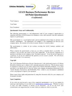
8 Frequency analysis is the essence of Vibration analysis and enables the satisfactory resolution of most machine problems. It is important to understand the relationship between the TIME WAVEFORM and the FREQUENCY SPECTRUM. On the following page is a sketch showing a geared motor producing three different forms of Vibration . There is Vibration from motor unbalance, Vibration from gearing and bearings. An accelerometer placed at any one point on the geared motor will measure a COMPLEX Vibration waveform as shown in the time drawing on the left side. This is the summation of all the Vibration present at that location. Spectrum analysis enables us to untangle this complex waveform and make a representation of its original components on a diagram showing frequency on the X-axis and amplitude vertically.
9 This is known as a Vibration SPECTRUM and is extremely valuable for fault diagnosis. The way the diagram has been drawn shows that the process is like looking at the Vibration from two directions at right angles to each other. From the time-direction we see the Phone: Fax: Email: Website: +61 (0) 402 731 563 +61 (8) 9457 8642 5 algebraic summation of all the individual frequencies present. From the spectrum-direction we see the location and amplitude of each frequency component. The conversion from Time to Frequency is achieved by use of an algorithm called the Fast Fourier Transform (known as an FFT).
10 The underlying principle was first postulated by Baron Fourier in the 19th century who stated that any periodic curve, no matter how complex, can be considered as comprising a number of pure sinusoidal curves with harmonically related frequencies. OPTIONAL MATERIAL further explaining the proper use of spectrum analysis . There are some important technical considerations that need to be understood by the engineer using FFT systems. a) Anti-Aliasing Filters. The first part of the process is to digitise the data. The fundamental rule of conversion from analogue to digital data is to ensure that a low-pass filter is installed so that the signal to be digitised contains no frequencies above half the sampling frequency.