Transcription of FX07 Field Controller Technical Bulletin
1 Technical Bulletin FX07 Terminal Unit Controller Issue Date June 9, 2014 2014 Johnson Controls, Inc. 1 Code No. LIT-12011269 FX07 Field Controller Introduction to FX07 Field Controller .. 4 Features ..5 Installation .. 6 North American Emissions Compliance ..8 Installation Procedures .. 8 Mounting the FX07 Controller ..8 Electronic Circuit Isolation Diagram ..11 Powering the FX07 Controller - 24 VAC Models ..12 Powering the FX07 Controller - 90 to 240 VAC Models (Models Unavailable in North America) ..13 Connection Details for FX07 Controller ..14 Jumper Settings for FX07 Controller ..17 N2 Open Communication Card ..18 LONWORKS Communication Card ..21 RS-232C Communication Card ..23 Connecting the Modem ..25 BACnet Communication Card ..30 Room Command Modules ..34 Remote User Interfaces ..40 FX Programming Inputs and Outputs .. 44 Introduction .. 44 Inputs and Outputs Concepts .. 44 Detailed Inputs and Outputs Procedures .. 45 Analog Inputs ..45 Digital Inputs.
2 47 Analog Outputs ..48 Digital Outputs ..50 2 FX07 Field Controller Technical Bulletin Operation .. 54 Operation Concepts .. 54 Communication Services ..54 Event Management ..54 Trend Logging ..54 Time Scheduling ..54 User Interfaces ..54 Supervisory Option ..55 Application Configuration and Commissioning ..55 Security ..56 Application Upload/Download ..56 Detailed Operation Procedures .. 56 Communication Services ..56 Event Management ..57 Trend Logging ..58 Time Scheduling ..60 User Interfaces ..62 Integral Display Operation ..64 Supervisory Option ..76 Application Configuration and Commissioning ..79 Security ..87 Application Download ..90 Troubleshooting .. 96 Reading 9999 or Invalid from the Analog Inputs ..96 Specifications and Technical Data .. 97 Ordering Codes .. 97 Technical Specifications .. 104 I/O Technical Details ..104 FX07 Controller ..106 N2 Open BACnet MS/TP LONWORKS Communication ..108 FX07 Field Controller Technical Bulletin 3 FX Programming GSM Connection.
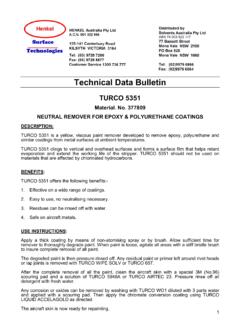
3 109 4 FX07 Field Controller Technical Bulletin Introduction to FX07 Field Controller Figure 1: FX07 Field Controller Models The FX07 is a Field Controller in the Facility Explorer range of products. The Controller is designed specifically for commercial Heating, Ventilating, Air Conditioning, and Refrigeration (HVACR) applications, such as small refrigeration compressors, close control units, rooftop air handlers, fan coil units, unit ventilators, and chilling or heating ceiling beam installations. The Controller has 17 physical inputs and outputs and supports a wide range of temperature sensors and actuating devices. Active sensors for the measurement of humidity, pressure, and other variables are also supported. The FX07 also includes an onboard real-time clock to support the start-stop scheduling of equipment and real-time based control sequences. The FX07 has an optional attractive Liquid Crystal Display (LCD) with a set of graphic status icons used in the most common HVACR applications.
4 The Controller also supports a remote panel or wall mounted Medium User Interface (MUI). Communication cards enable the Controller to integrate into an N2 Open, LONWORKS , or BACnet network of a building automation system. FX07 Field Controller Technical Bulletin 5 For stand-alone applications, the FX07 also features communications services to transmit event notification messages via Short Messaging Service (SMS) using an RS-232C Serial communication card and Global System for Mobile Communications (GSM) modem. Using the FX Tools software package, you can fully configure and program the FX07 for a wide range of commercial HVACR applications. Features The features of the FX07 include: fully programmable Controller using FX Tools software package RS-485 (N2 Open or BACnet Master-Slave/Token-Passing [MS/TP]) or LON TP/FT-10 (twisted pair/free topology) plug-in communication card for connection to a supervisory system as an alternative, an RS-232C communications port for a modem (or null modem) connection in stand-alone applications compatible with Global System for Mobile Communications (GSM) modems DIN rail mounting removable screw connectors for servicing operations 17 physical inputs and outputs including relays and triacs wide range of analog sensor inputs: passive temperature: A99, PT1000 Standard, PT1000 Extended Range, NTC 10k, and Ni1000 (Johnson Controls) active voltage: ratiometric and 0 - 10 VDC optional user interfaces.
5 Integral or remote real-time clock for time-based control sequences events displayed on user interface (up to 20 events) FX CommPro online software tool for commissioning and service operations FX Programming Key for easy application loading 6 FX07 Field Controller Technical Bulletin Installation This section takes you through the process of installing a FX07 Field Controller . ! WARNING: Risk of Electric Shock. Disconnect or isolate all power supplies before making electrical connections. More than one disconnect or isolation may be required to completely de-energize equipment. Contact with components carrying hazardous voltage can cause electric shock and may result in severe personal injury or death. AVERTISSEMENT: Risque de d charge lectrique. D brancher ou isoler toute alimentation avant de r aliser un branchement lectrique. Plusieurs isolations et d branchements sont peut- tre n cessaires pour -couper enti rement l'alimentation de l' quipement. Tout contact avec des composants conducteurs de tensions dangereuses risque d'entra ner une d charge lectrique et de provoquer des blessures graves, voire mortelles.
6 IMPORTANT: Use this FX07 Controller only as an operating control. Where fa ilure or malfunction of the FX07 could lead to personal injury or damage to the controlled equipment or other property, additional precautions must be designed into the control system. Incorporate and maintain other devices such as supervisory or alarm systems or safety or limit controls that are intended to warn of, or protect against, failure or malfunction of the FX07 Controller . IMPORTANT: In North America, the Controller is intended for installation with Class 2 inputs and outputs only where no special electrical safety mounting precautions are generally necessary. These controllers are UL Listed as Open Energy Management Equipment per UL 916. FX07 Field Controller Technical Bulletin 7 IMPORTANT: Before specifying the FX07 for plenum applications, verify acceptance of exposed plastic materials in plenum areas with the local building authority. Building codes for plenum requirements vary by location.
7 Some local building authorities accept compliance to UL 1995, Heating and Cooling Equipment, whereas others use different acceptance criteria. IMPORTANT: Cables and wiring at Safety Extra Low Voltage (SELV) and Class 2 wiring (North America) must be separated from power line voltage wiring. A minimum separation distance of 30 cm (12 in.) is recommended. Do not run extra low voltage cables parallel to power line voltage cables for long distances greater than 3 m (10 ft). Do not run extra low voltage wiring close to transformers or high frequency generating equipment. 8 FX07 Field Controller Technical Bulletin North American Emissions Compliance United States This equipment has been tested and found to comply with the limits for a Class A digital device pursuant to Part 15 of the FCC Rules. These limits are designed to provide reasonable protection against harmful interference when this equipment is operated in a commercial environment. This equipment generates, uses, and can radiate radio frequency energy and, if not installed and used in accordance with the instruction manual, may cause harmful interference to radio communications.
8 Operation of this equipment in a residential area is likely to cause harmful interference, in which case the user will be required to correct the interference at his/her own expense. Canada This Class (A) digital apparatus meets all the requirements of the Canadian Interference-Causing Equipment Regulations. Cet appareil num rique de la Classe (A) respecte toutes les exigences du R glement sur le mat riel brouilleur du Canada. Installation Procedures ! WARNING: Risk of Electric Shock. Disconnect power supply before making electrical connections. Contact with components carrying hazardous voltage can cause electric shock and may result in injury or death. AVERTISSEMENT: Risque de d charge lectrique. D brancher l'alimentation avant de r aliser tout branchement lectrique. Tout contact avec des composants conducteurs de tensions dangereuses risque d'entra ner une d charge lectrique et de provoquer des blessures graves, voire mortelles. Mounting the FX07 Controller Follow these instructions to properly install and connect the FX07.
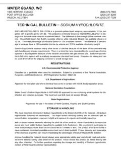
9 108 mm ( in.)49 mm ( in.)118 mm( in.)145 mm( in.) FX07 Field Controller Technical Bulletin 9 108 mm ( in.)49 mm ( in.)62 mm ( in.)118 mm( in.)145 mm( in.) Figure 2: Mounting Dimensions for FX07 (Shown with and without Optional Display) The Controller mounts on a 35 mm ( in.) DIN rail within a protective enclosure. The horizontal position provides the most efficient cooling of the Controller through the ventilation slots. IMPORTANT: The Complementary Metal Oxide Semiconductor (CMOS) circuits in the Controller are sensitive to static electricity. Take suitable precautions. To mount the FX07 Controller : 1. Set the jumpers and address switches before you install the Controller . For more information, see Jumper Settings for FX07 Controller . 2. Locate the spring-loaded retaining clips at the back of the Controller (on the lower edge of the DIN rail). 3. Press the Controller upwards against the clip, engage the upper lugs over the upper edge of the rail, and release downwards.
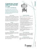
10 4. To remove the Controller , push the Controller up against the retaining clips and then tilt the top forward to release the top lugs from the DIN rail. You can also remove the Controller by removing the lower screw terminals and carefully inserting a screw driver in Slot A. You can then pull out the retaining clip to release the Controller from the DIN rail. 10 FX07 Field Controller Technical Bulletin ig: F X07_Moun ti ng DIN Figure 3: Mounting the FX07 on a DIN Rail 5. Make wiring terminations with the detachable screw connectors. The screw terminals are included in a separate bag within the package. The analog and digital input and analog output terminals on the upper side of the Controller accept 1 x mm2/16 AWG, or 2 x mm/20 AWG cables. The power input and relay and triac output terminals accept 1 or 2 x mm2/16 AWG cables. N o te : These terminals may carry voltages up to 250 VAC (Europe only). 6. Make the terminations to the Supervisory Link, Local Link Bus, and Remote Display, as required, via the connectors provided with the Controller .