Transcription of FXZQ-M 4-Way Ceiling Mounted Cassette Unit (2' × 2')
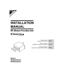
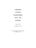
1 EDUS 39 - 800 - F9_bAMERICASFXZQ-M4-Way Ceiling Mounted Cassette unit (2' 2')EDUS39-800-F9_bFXZQ-M1 FXZQ-M4-Way Ceiling MountedCassette unit (2 2 )1. External 22. Specifications .. 33. Dimensions .. 54. Piping Diagrams .. 75. Wiring 86. Electric 97. Capacity Tables .. Cooling Capacity .. Heating Capacity .. 118. Air Velocity and Temperature Distributions (Reference Data).. 129. Sound Levels .. and Operation .. Center of Gravity .. Installation Manual / Indoor Installation Manual / Decoration .. 37 External AppearanceEDUS39-800-F9_b2 FXZQ-M1. External AppearanceFXZQ07~18 MEDUS39-800-F9_bSpecificationsFXZQ-M32.
2 Specifications4-Way Ceiling Mounted Cassette unit (2 2 )Notes: 1 Nominal cooling capacities are based on the following conditions: Return air temperature: 80 FDB, 67 FWBO utdoor temperature: 95 FDB Equivalent ref. piping length: 25ft (Horizontal) 2 Nominal heating capacities are based on the following conditions:Return air temperature: 70 FDB. Outdoor temperature: 47 FDB, 43 FWBE quivalent ref. piping length: 25ft (Horizontal)3 Capacities are net, including a deduction for cooling (an addition for heating) for indoor fan motor heat. 4 Anechoic chamber conversion value, measured under JISB8616 conditions. During actual operation, these values are normally somewhat higher as a result of installation Refer to page 9 for Power 1 Cooling CapacityBtu/h7,5009,50012,000 2 Heating CapacityBtu/h8,70011,10014,000 Casing / ColorGalvanized Steel / Non PaintedGalvanized Steel / Non PaintedGalvanized Steel / Non PaintedDimensions: (H W D)in10-1/4 (11-3/8 ) 10-3/4 10-3/4( ): include Electrical Component box10-1/4 (11-3/8 ) 10-3/4 10-3/4( ): iinclude Electrical Component box10-1/4 (11-3/8 ) 10-3/4 10-3/4( ).
3 Include Electrical Component boxCoil (Cross Fin Coil)Rows Stages FPI2 10 172 10 172 10 17 Face Areaft FanTurbo FanTurbo FanMotor Output (High)W555555 Air Flow Rate (H/L)cfm320/247320/247335/265 DriveDirect DriveDirect DriveDirect DriveTemperature ControlMicroprocessor Thermostatfor Cooling and HeatingMicroprocessor Thermostatfor Cooling and HeatingMicroprocessor Thermostatfor Cooling and HeatingAir FilterResin Net(with Mold Resistant)Resin Net(with Mold Resistant)Resin Net(with Mold Resistant)Piping ConnectionsLiquid Pipesin 1/4 (Flare Connection) 1/4 (Flare Connection) 1/4 (Flare Connection)Gas Pipesin 1/2 (Flare Connection) 1/2 (Flare Connection) 1/2 (Flare Connection)Drain PipeinVP20 External Dia.
4 1-1/8 Internal Dia. 7/8VP20 External Dia. 1-1/8 Internal Dia. 7/8VP20 External Dia. 1-1/8 Internal Dia. 7/8 Machine Weight (Mass)Lbs424242 4 Sound Level (H/L)dBA31/2933/2941/34 Safety DevicesFuseFuseFuseRefrigerant ControlElectronic Expansion ValveElectronic Expansion ValveElectronic Expansion ValveConnectable outdoor unitR-410A SeriesR-410A SeriesR-410A SeriesDecoration Panels(Option)ModelBYFQ60 BUBYFQ60 BUBYFQ60 BUColorWhite (RAL 9010)White (RAL 9010)White (RAL 9010)Dimensions: (H W D)in2-1/4 27-58 27-5/82-1/4 27-58 27-5/82-1/4 27-58 27-5/8 WeightLbs666 Standard AccessoriesInstallation and Operation manual, Paper pattern for installation, Drain hose, Clamp metal, Washer fixing plate, Sealing pads, Clamps, Screws, Washer for hanger bracket, Insulation for and Operation manual, Paper pattern for installation, Drain hose, Clamp metal, Washer fixing plate, Sealing pads, Clamps, Screws, Washer for hanger bracket, Insulation for and Operation manual, Paper pattern for installation, Drain hose, Clamp metal, Washer fixing plate, Sealing pads, Clamps, Screws, Washer for hanger bracket, Insulation for.
5 3TW30721-1()()()SpecificationsEDUS39-800 -F9_b4 FXZQ-M4-Way Ceiling Mounted Cassette unit (2 2 )Notes: 1 Nominal cooling capacities are based on the following conditions: Return air temperature: 80 FDB, 67 FWB Outdoor temperature: 95 FDBE quivalent ref. piping length: 25ft (Horizontal) 2 Nominal heating capacities are based on the following conditions: Return air temperature: 70 FDB. Outdoor temperature: 47 FDB, 43 FWBE quivalent ref. piping length: 25ft (Horizontal)3 Capacities are net, including a deduction for cooling (an addition for heating) for indoor fan motor heat. 4 Anechoic chamber conversion value, measured under JISB8616 conditions.
6 During actual operation,these values are normally somewhat higher as a result of installation Refer to page 9 for Power 1 Cooling CapacityBtu/h18,000 2 Heating CapacityBtu/h21,000 Casing / ColorGalvanized Steel / Non PaintedDimensions: (H W D)in10-1/4 (11-3/8 ) 10-3/4 10-3/4 Coil (Cross Fin Coil)Rows Stages FPI2 10 17 Face Areaft FanMotor Output (High)W55 Air Flow Rate (H/L)cfm495/353 DriveDirect DriveTemperature ControlMicroprocessor Thermostat for Cooling and HeatingAir FilterResin Net(with Mold Resistant)Piping ConnectionsLiquid Pipesin 1/4 (Flare Connection)Gas Pipesin 1/2 (Flare Connection)Drain PipeinVP20 External Dia.
7 1-1/8 Internal Dia. 7/8 Machine Weight (Mass)Lbs42 4 Sound Level (H/L)dBA41/34 Safety DevicesFuseRefrigerant ControlElectronic Expansion ValveConnectable outdoor unitR-410A SeriesDecoration Panels(Option)ModelBYFQ60 BUColorWhite (RAL 9010)Dimensions: (H W D)in2-1/4 27-58 27-5/8 WeightLbs6 Standard AccessoriesInstallation and Operation manual, Paper pattern for installation, Drain hose, Clamp metal, Washer fixing plate, Sealing pads, Clamps, Screws, Washer for hanger bracket, Insulation for :3TW30721-1()EDUS39-800-F9_bDimensionsFX ZQ-M53. DimensionsFXZQ07M7 VJUFXZQ09M7 VJUFXZQ12M7 VJUFXZQ18M7 VJU3TW30724-2 DimensionsEDUS39-800-F9_b6 FXZQ-M3TW30724-3 FXZQ07~18M7 VJU+BYFQ60B8W1 BYFQ60B8W1 UEDUS39-800-F9_bPiping DiagramsFXZQ-M74.
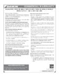
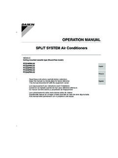
8 Piping DiagramsR1T : Thermistor for suction air temperatureR2T : Thermistor for liquid line temperatureR3T : Thermistor for gas line temperatureCapacityGASL iquid07/09/12/18M 1/2 1/4C:4D040157 Heat exchangerGas piping connection portLiquid piping connection portFanR3TR1 TElectronicexpansion valveFilterFilterR2 TWiring DiagramsEDUS39-800-F9_b8 FXZQ-M5. Wiring DiagramsFXZQ07M/09M/12M/18M7 VJUTHERMISTOR (COIL-LIQUID)MOTOR (DRAIN PUMP)LIGHT EMITTING DIODE(DEFROST-ORANGE)TRIACCONNECTOR(WIRI NG ADAPTOR FORELECTORICAL APPENDICES)THERMAL PROTECTOR (M1F EMBEDDED)MOTOR (SWING FLAP)TERMINAL BLOCKCONNECTOR(ADAPTOR FOR WIRING)LIGHT EMITTING DIODE (ON-RED)ELECTRONIC EXPANSION VALVECONNECTOR FOR OPTIONAL PARTSPRINTED CIRCUIT BOARDMOTOR (INDOOR FAN)THERMISTOR (AIR)PUSH BUTTON (ON/OFF)PRINTED CIRCUIT BOARDSELECTOR SWITCH(WIRELESS ADDRESS SET)LIGHT EMITTING DIODE(TIMER-GREEN)THERMISTOR (COIL-GAS)SELECTOR SWITCH (MAIN/SUB)LIGHT EMITTING DIODE(SERVICE MONITOR GREEN)FLOAT SWITCHTHERMISTOR (AIR)
9 PRINTED CIRCUIT BOARDFUSE ( B , 5A, 250V)CAPACITOR (M1F)WIRELESS REMOTE CONTROLLER(RECEIVER/DISPLAY unit )MAGNETIC RELAY (M1P)LIGHT EMITTING DIODE(FILTER SIGN-RED)WIRED REMOTE CONTROLLERTERMINAL BLOCKSELECTOR SWITCH (MAIN/SUB)F1UR1TY1EV1 TRX1MX2MX16AH4 PHAPH1PQ1MA4PX18AM1 FBS1SS1H2PA1PR1TH3PT1RS1LM1SA3PM1 PKPRSS2R2TC1SS1R3 TTRANSFORMER (208-230V/22V)WHTX25AX13AX7 AWHTCONTROL BOXX1MA1PX2MT1RC1C1X2MV1 TRX1ML1L2X18AA1PX12 AREDL2M~t t t t X30 ANOTE) 4 INPUT FROM OUTSIDEBLKQ1 MKPRX3AX4AP2 HAPYLWREDGRN/YLWR3 TWHTX28 AMYLWWIRED REMOTECONTROLLERYLWSS1 NOTE) 2 TRANSMISSION WIRINGCENTRAL REMOTE CONTROLLERBS1X16 ABLKX8AT2F1T1P2F2P1X11AR2TR1TM1 FSS1 PNKYLWR1TS1 LBLUM1 PSS2MX31 AMSWL1Y1EF1 UORGM1SP1H1PH4PH3 PNOTE) 3X23AA3PX1AA4 PRECEIVER/DISPLAY UNITX1AH2PX2AA1PX1AX23 ANOTE) 3T1 RPOWER SUPPLY208-230V~60 HzNOTES)1.
10 : TERMINAL , : CONNECTOR : FIELD WIRING2. IN CASE USING CENTRAL REMOTE CONTROLLER, CONNECT IT TO THE unit IN ACCORDANCE WITH THE ATTACHED INSTALLATION X23A IS CONNECTED WHEN THE WIRELESS REMOTE CONTROLLER KIT IS BEING WHEN CONNECTING THE INPUT WIRES FROM OUTSIDE, FORCED OFF OR ON/OFF CONTROL OPERATION CAN BE SELECTED BY REMOTE CONTROLLER. IN DETAILS, REFER TO THE INSTALLATION MANUAL ATTACHED THE REMOTE CONTROLLER MODEL VARIES ACCORDING TO THE COMBINATION SYSTEM, CONFIRM ENGINEERING MATERIALS AND CATALOGS, ETC. BEFORE SYMBOLS SHOW AS FOLLOWS: RED : RED BLK : BLACK WHT : WHITE YLW : YELLOW PNK : PINK ORG : ORANGEGRN : GREEN BLU : BLUEC:3D059263C:3TW30726-1 EDUS39-800-F9_bElectric CharacteristicsFXZQ-M96.