Transcription of G6S - Omron
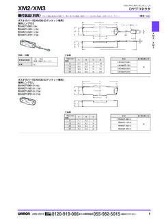
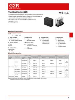
1 1G6SG6 SSurface-mounting RelayCompact, Industry-Standard 2-pole relay, designed to switch 2A Signal Loads. Long terminals for ideal for soldering and mounting reliability. (Surface mounting terminal models) Space-saving inside-L terminal. (Surface mounting terminal models) Unique terminal structure, designed to withstand IRS soldering processes. (Surface mounting terminal models) High dielectric strength (2,000 VAC) and impulse withstand voltage between coil and contacts (2,500 V, 2 10 s: Telcordia requirements). Ultra-miniature at mm (H) mm (W) 15 mm (L). Models available with BSI (EN62368-1) supplementary insulation certification. (-Y type) Model Number Legend Ordering Information Surface mounting terminal standard modelsNote 1. When ordering, add the rated coil voltage to the model number. Example: G6S-2F DC3 However, the notation of the coil voltage on the product case as well as on the packing will be marked as @@ ordering tape packing, add -TR" to the model sure since -TR" is n ot part of the relay model number, it is not marked on the relay ordering tape packing, minimum order unit is 2 reels (400 pcs 2 = 800 pcs).
2 Note mounting terminal (SMT) standard models are shipped in moisture-proof CompliantPackingTube PackingTape PackingEnclosure ratingRelay FunctionContact formModelRated coil voltageMinimum packing unitModelRated coil voltageMinimum packing unitMinimum ordering unit(tape packing)Fully sealedSingle-side stableDPDT (2c)G6S-2FG6S-2G3 VDC50 pcs/tubeG6S-2F-TRG6S-2G-TR3 VDC400 pcs/reel800 pcs/2 VDC5 VDC5 VDC12 VDC12 VDC24 VDC24 VDCG6S-2F-YG6S-2G-Y5 VDCG6S-2F-Y-TRG6S-2G-Y-TR5 VDC12 VDC12 VDC24 VDC24 VDCS ingle-winding latchingG6SU-2FG6SU-2G3 VDCG6SU-2F-TRG6SU-2G-TR3 VDC5 VDC5 VDC12 VDC12 VDC24 VDC24 VDCG6SU-2F-YG6SU-2G-Y5 VDCG6SU-2F-Y-TRG6SU-2G-Y-TR5 VDC12 VDC12 VDC24 VDC24 VDCD ouble-winding latchingG6SK-2FG6SK-2G3 VDCG6SK-2F-TRG6SK-2G-TR3 VDC5 VDC5 VDC12 VDC12 VDC24 VDC24 VDC1. Relay FunctionNone : Single-side stableU: Single-winding latchingK: Double-winding latching2. Number of poles/ Contact form2: 2-pole/DPDT (2c)G6S@-@@ Terminal ShapeNone : PCB terminalsF: Outside-L surface mounting terminalsG: Inside-L surface mounting terminals4.
3 Approved StandardsNone : UL, CSAY: UL, CSA, BSI (EN62368-1) Application Examples Telecommunication equipment Measurement devices Office automation machines Audio-visual products. Security equipment Building automation equipment Industrial equipment Amusement equipment Home appliancesRated coil voltage2G6 SSurface-mounting RelayG6S PCB Terminal Standard ModelsNote 1. When ordering, add the rated coil voltage to the model : G6S-2 DC3 However, the notation of the coil voltage on the product case as well as on the packing will be marked as @@ terminal standard types do not require moisture proof packaging and therefore shipped in non-moisture-proof package. Ratings Single-side Stable Model Note 1. The rated current and coil resistance are measured at a coil temperature of 23 C with a tolerance of 10%. 2. Operating characteristics are measured at a coil temperature of 23 C. 3. The maximum voltage is the highest voltage that can be imposed on the relay coil.
4 Single-winding Latching ModelNote 1. The rated current and coil resistance are measured at a coil temperature of 23 C with a tolerance of 10%. 2. Operating characteristics are measured at a coil temperature of 23 C. 3. The maximum voltage is the highest voltage that can be imposed on the relay coil. Double-winding Latching ModelNote 1. The rated current and coil resistance are measured at a coil temperature of 23 C with a tolerance of 10%. 2. Operating characteristics are measured at a coil temperature of 23 C. 3. The maximum voltage is the highest voltage that can be imposed on the relay ratingRelay FunctionSingle-side stableSingle-winding latchingDouble-winding latchingMinimum packing unitContact formModelRated coil voltageModelRated coil voltageModelRated coil voltageFully sealedDPDT (2c)G6S-23 VDCG6SU-23 VDCG6SK-23 VDC50 VDC5 VDC5 VDC5 VDC12 VDC12 VDC12 VDC24 VDC24 VDC24 VDCG6S-2-Y5 VDCG6SU-2-Y5 VDC 12 VDC12 VDC24 VDC24 VDCItemRated current (mA)Coil resistance ( )Must operate voltage (V)Must release voltage (V)Max.
5 Voltage (V)Power consumption(mW)ModelRated (at 23 C)Approx. , ,880170% (at 23 C)Approx. 200G6S-2-YG6S-2F-YG6S-2G-YDC540 12575% (at 23 C)Approx. ,504 Approx. 230 ItemRated current (mA)Coil resistance ( )Must operate voltage (V)Must release voltage (V)Max. voltage (V)Power consumption(mW)ModelRated 9075% (at 23 C)Approx. , ,840 Approx. (at 23 C)Approx. , ,114 ItemRated current (mA)Coil resistance ( )Must operate voltage (V)Must release voltage (V)Max. voltage (V)Power consumption(mW)ModelRated 4575% (at 23 C)Approx. ,920140% (at 23 C)Approx. 300 Rated coil voltage ContactsItemLoadResistive loadContact typeBifurcated crossbarContact material Ag (Au-Alloy)Rated A at 125 VAC; 2 A at 30 VDCR ated carry current2 AMax. switching voltage250 VAC, 220 VDCMax. switching current2 A3G6 SSurface-mounting RelayG6S CharacteristicsNote: The above values are initial values.
6 * contact resistance was measured with 10 mA at 1 VDC with a voltage drop method.* insulation resistance was measured with a 500 VDC megohmmeter applied to the same parts as those used for checking the dielectric strength (except between the set and reset coil).* value was measured at a switching frequency of 120 operations/min and the criterion of contact resistance is 50 . This value may vary, depending on switching frequency, operating conditions, expected reliability level of the relay, etc. It is always recommended to double-check relay suitability under actual load conditions. Engineering DataItemRelay FunctionSingle-side Stable G6S-2, G6S-2F, G6S-2 GSingle-winding LatchingG6SU-2, G6SU-2F, G6SU-2 GDouble-winding LatchingG6SK-2, G6SK-2F, G6SK-2 GSingle-side StableG6S-2F-Y, G6S-2G-Y, G6S-2-YSingle-winding LatchingG6SU-2-Y,G6SU-2F-Y,G6SU-2G-YCont act resistance *175 m (set) time4 ms (reset) time4 ms set/reset pulse width 10 ms 10 msInsulation resistance *21,000 M min.
7 (at 500 VDC)Dielectric strengthBetween coil and contacts2,000 VAC, 50/60 Hz for 1 min1,000 VAC, 50/60 Hz for 1 min2,000 VAC, 50/60 Hz for 1 minBetween contacts of different polarity1,500 VAC, 50/60 Hz for 1 minBetween contacts of the same polarity1,000 VAC, 50/60 Hz for 1 minBetween set and reset coil 500 VAC, 50/60 Hz for 1 min Insulation distanceBetween coil and contactsClearance: 1 mm, Creepage: mmClearance: 2 mm, Creepage: 2 mmImpulse withstand voltageBetween coil and contacts2,500 V (2 10 s); 1,500 V (10 160 s)1,500 V (10 160 s)2,500 V (2 10 s); 1,500 V (10 160 s)Between contacts of different polarity2,500 V (2 10 s); 1,500 V (10 160 s)Between contacts of the same polarity1,500 V (10 160 s)Vibration resistanceDestruction10 to 55 to 10 Hz, mm single amplitude (5 mm double amplitude)Malfunction10 to 55 to 10 Hz, mm single amplitude ( mm double amplitude)Shock resistanceDestruction1,000 m/s2 Malfunction750 m/s2 DurabilityMechanical100,000,000 operations min.
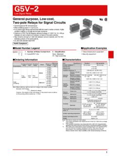
8 (at 36,000 operations/hr)Electrical100,000 operations min. for AC (at 1,800 operations/h with rated load) 100,000 operations min. for DC (at 1,200 operations/h with rated load)Failure rate (P level) (reference value) *310 A at 10 m VDCA mbient operating temperature-40 C to 85 C (with no icing or condensation), and -40 C to 70 C (with no icing or condensation) only for double-winding latching 24 VDC and -Y type 24 VDCA mbient operating humidity5% to 85%WeightApprox. 2 g Maximum Switching Capacity DurabilityG6S-2F(G) Ambient Temperature vs. Maximum Voltage(Single-side Stable) Ambient Temperature vs. Maximum Voltage(Latching)Note: Maximum voltage is the maximum voltage that can be applied to the Relay coil. Ambient Temperature vs. Switching Current(Single-side Stable) Ambient Temperature vs. Switching Current(Latching) Ambient Temperature vs. Must Operate or Must Release VoltageG6S-2F(G) Shock MalfunctionG6S-2F(G)Conditions: Shock is applied in X, Y, and Z directions three times each with and without energizing the Relays to check the number of contact 30 50 70 100 300 500 700 1,000 Switching voltage (V)Switching current (A) resistive loadAC resistive load5003001005030105310 1 2 3 Switching current (A)125 VAC resistive loadAmbient temperature 23 CSwitching frequency: 1,800 operations/h30 VDC resistive loadAmbient temperature 23 CSwitching frequency: 1,200 operations/hDurability ( 104 operations) to 12 VDCG6S-Y24 VDCG6S24 VDCG6S-Y12 VDC max.
9 40 20 0 20 40 60 80 100250200150100500 Ambient temperature ( C)Maximum voltage (%)250200150100500G6 SUG6SK12 VDC VDCM aximum voltage (%) 40 20 0 20 40 60 80 100250200150100500 Ambient temperature ( C)G6S12 VDC VDCG6S-Y12 VDC VDCS witching current (A)321040 50 60 70 80 90 100 Ambient temperature ( C)321040 50 60 70 80 90 100 Ambient temperature ( C)G6SK 24 VDCG6SU 12 VDC 24 VDCG6SK 12 VDC current (A)100806040200 60 40 20 0 20 40 60 80 100 120 Ambient temperature ( C)Sample: G6S-2F Number of Relays: 10 operate voltageMust release the basis of rated voltage (%)ZZ'YY'XX'2004006008001,0001,0001,0001 ,0001,0008006004002001,000 Shock directionUnit: m/s2 Sample: G6S-2 FNumber of Relays: 10 pcsXX'EnergizedZZ'YY'De- energized4G6 SSurface-mounting RelayG6S* tests were conducted at an ambient temperature of 23 C.
10 * contact resistance data are periodically measured reference values and are not values from each monitoring operation. Contact resistance values will vary according to the switching frequency and operating environment, so be sure to check operation under the actual operating conditions before use.* characteristics depend on the PCB to which the Relay is mounted. Always check these characteristics, including durability, in the actual machine before use. electrical Endurance (with Must Operate and Must Release Voltage) *1G6S-2F(G) electrical Endurance (Contact Resistance) *1G6S-2F(G) electrical Endurance (with Must Operate and Must Release Voltage) *1G6S-2F(G) electrical Endurance (Contact Resistance) *1G6S-2F(G) Contact Reliability Test (Contact Resistance) *1, *2G6S-2F(G) Must Operate and Must Release Time Distribution *1G6S-2F(G) Distribution of Bounce Time *1G6S-2F(G) Mutual Magnetic InterferenceG6S-2F(G) External Magnetic InterferenceG6S-2F(G)(Average value)(Average value)(Average value) Mutual Magnetic InterferenceG6S-2F(G) High-frequency Characteristics (Isolation) *1, *2G6S-2F(G)(Average value (initial)) High-frequency Characteristics (Insertion Loss) *1, *3G6S-2F(G)(Average value (initial)) High-frequency Characteristics (Return Loss, ) *1, *3G6S-2F(G)(Average value (initial))