Transcription of DC Power Relays
1 Compact models added tofurther expand SeriesG9 ECG9 EBG9 EAG9EA/G9EB/G9 ECDC Power RelaysA Leader in Clean Energy with Compact, Quiet, Energy-efficient DesignsDC Control in a RelayThe G9EA is Power Relays that Interrupt high -capacity DC Loads and high - voltage DC Circuits in a Compact, Low-noise DesignDCP OWE RR E LAYM agnet:Arc-containing effectGas-filled construction(contactor):Arc-cooling effect In the endeavors to prevent global warming, air pollution, and the depletion of oil resources, much attention is being given to increasing the efficiency of AC-to-DC Power conversion and distributed Power generation.
2 DC contactors and circuit-breakers, however, are disadvantaged by their noise and bulk. OMRON has improved on the standard DC circuit that switches using a contactor or circuit-breaker by developing the G9EA/G9EB/G9EC DC Power Relay Series. These Relays enable switching high - voltage and high -capacity loads. The switch's gas-filled construction allows a considerable reduction in the relay switch size, while also lowering the operating noise during load switching. Furthermore, the new design has decreased the Power consumption of the coil and achieved long-term contact with the same class (load switching) of G9EA DC Power Switching TechnologiesSpace-savingNo arc space neededPower-saving30% less Power consumptionCompact70% less volumeQuiet50% lower operating noiseSafe,reliable design*Smaller and quieter for a variety of DC applicationsAutomobilesHybrid cars, fuel-cell cars, compact electric passenger vehicles, VehiclesBattery-operated golf carts, forklifts, AGV (automated guided vehicles)
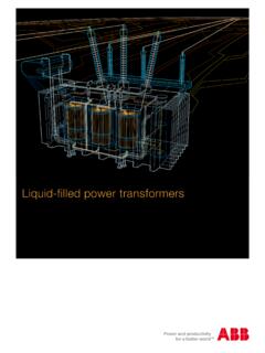
3 , battery-powered agricultural equipment, Power and Distributed Power GenerationWind-powered or photovoltaic Power generation systems, fuel-cell cogeneration systems, Industrial EquipmentInverters, UPS, Power supplies, robots, machining centers, elevators, escalators, medical equipment, testing equipment (batteries, fuel cells), switchingGas-cooled arcMagnetic arc controlApplications DC Power Relays Selection Guide3DC Power RelaysSelection GuideOMRON DC Power Relays Interrupt high -capacity DC Loads while Enabling Compact, Low-noise, Safe Applications List of DC Power RelaysModelG9 EAG9 ECG9 EBG9EA-1(-B)G9EA-1(-B)-CAG9EC-1(-B)G9EB- 1-BClassificationSwitching/current conductionHigh-current conductionSwitching/current conductionSwitching/current conductionAppearanceFeaturesStandard modelCompact, carries/switches 400-V, 60-A loadsCarries 100 ALow contact resistance when carrying currentLargest capacity in seriesCarries/switches 400-V, 200-A loadsSmallest in seriesCarries/switches 250-V, 25-A loadsContactsContact formSPST-NOContact structureDouble-break, singleContact resistance30 m max.
4 ( m typical)10 m max. ( m typical)30 m max. ( m typical)30 m voltage drop V max. (for a carry current of 60 A) V max. (for a carry current of 100 A) V max. (for a carry current of 200 A) V max. (for a carry current of 25 A)Electrical endurance120 VDC, 100 A, 3,000 operations VDC, 30 A, 1,000 operations VDC, 200 A, 3,000 operations VDC, 25 A, 30,000 operations VDC, 60 A, 3,000 operations VDC, 30 A, 2,500 operations VDC, 30 A, 30,000 operations switching current100 A30 A200 A25 ARated carry current20018016014012010080604020 Short-time carry cur-rent100 A (10 min)150 A (10 min)300 A (15 min)50 A (5 min), 40 A (10 min)Maximum interruption current600 A at 300 VDC (5 times)---1,000 A at 400 VDC(10 times)100 A at 250 VDC(5 times)Overload interruption180 A at 400 VDC(100 times min.)
5 100 A at 120 VDC (150 times min.)700 A at 400 VDC (40 times min.)50 A at 250 VDC(50 times min.)Reverse polarity inter-ruption 60 A at 200 VDC(1,000 times min.)--- 200 A at 200 VDC(1,000 times min.)---CoilRated voltage12, 24, 48, 60, and 100 VDCP ower consumptionApprox. 5 to WApprox. 11 WApprox. 2 WMechanical endurance200,000 operations ,000 operations IN JAPANCONTACT:60A 400 VDCLot No. 1362K1-00012(-)1(+) IN JAPANCONTACT:200A 400 VDCLot No. 1362K1-00012(-)1(+) IN JAPANCONTACT:25A 250 VDCLot No. 0424Y1-0001243160255860 A100 A200 A25 A4DC Power Relays Selection GuideNote: insulation resistance was measured with a 500-VDC impulse withstand voltage was measured with a JEC-212 (1981) standard impulse voltage waveform ( 50 s).
6 Insulation resistance (See note 2.)Between coil and contacts1,000 M contacts of the same polarity1,000 M strengthBetween coil and contacts2,500 VAC, 1 minBetween contacts of the same polarity2,500 VAC, 1 minImpulse withstand voltage (See note 3.)4,500 VAmbient operating temperature 40 to 70 C (with no icing or condensation) 40 to 50 C (with no icing or condensation) 40 to 70 C (with no icing or condensation)Ambient operating humidity5% to 85%TerminalsScrew terminalsYesYesYesLead wire outputYesYes---WeightApprox. 310 gApprox. 560 gApprox. 135 gRefer to page 51117 ModelG9 EAG9 ECG9 EBG9EA-1(-B)G9EA-1(-B)-CAG9EC-1(-B)G9EB- 1-BClassificationSwitching/current conductionHigh-current conductionSwitching/current conductionSwitching/current conductionAppearanceFeaturesStandard modelCompact, carries/switches 400-V, 60-A loadsCarries 100 ALow contact resistance when carrying currentLargest capacity in seriesCarries/switches 400-V, 200-A loadsSmallest in seriesCarries/switches 250-V, 25-A loadsG9EA-1-B12 VDCMADE IN JAPANCONTACT:60A 400 VDCLot No.
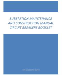
7 1362K1-00012(-)1(+) IN JAPANCONTACT:200A 400 VDCLot No. 1362K1-00012(-)1(+) IN JAPANCONTACT:25A 250 VDCLot No. 0424Y1-00012431602558 DC Power Relays (60-A, 100-A Models) G9EA-15DC Power Relays (60-A, 100-A Models)G9EA-1DC Power Relays Capable of Interrupting high - voltage , high -current Loads A compact relay (73 x 36 x mm (L x W x H)) capable of switching 400-V 60-A DC loads. (Capable of interrupting 600 A at 300 VDC max.) The switching section and driving section are gas-injected and hermetically sealed, allowing these compact Relays to interrupt high -capacity loads. The sealed construction also requires no arc space, saves space, and helps ensure safe applications.
8 Downsizing and optimum design allow no restrictions on the mounting direction. Terminal Cover and DIN Track Adapters are also available for in-dustrial applications. UL/CSA standard UL508 :Refer to Precautions on page Number Structure Model Number Legend1. Number of Poles1:1 pole2. Contact FormBlank: SPST-NO3. Coil screw terminalsBlank: Lead wire output4. Special FunctionsCA: high -current conduction (100 A)Ordering Information List of ModelsNote: M5 screws are provided for the contact terminal screws are provided for the coil terminal 34G9EA-@-@-@-@ModelsTerminalsContact formRated coil voltageModelCoil terminalsContact terminalsSwitching/current con-duction modelsScrew terminals (See note 2.)
9 Screw terminals (See note 1.)SPST-NO12 VDC24 VDC48 VDC60 VDC100 VDCG9EA-1-BLead wiresG9EA-1 high -current conduc-tion modelsScrew terminals (See note 2.)G9EA-1-B-CALead wiresG9EA-1-CA6DC Power Relays (60-A, 100-A Models) G9EA-1 Specifications RatingsCoilNote: figures for the rated current and coil resistance are for a coil temperature of 23 C and have a tolerance of 10%. figures for the operating characteristics are for a coil temperature of 23 figure for the maximum voltage is the maximum voltage that can be applied to the relay CharacteristicsNote: above values are initial values at an ambient temperature of 23 C unless otherwise contact resistance was measured with 1 A at 5 VDC using the voltage drop insulation resistance was measured with a 500-VDC impulse withstand voltage was measured with a JEC-212 (1981) standard impulse voltage waveform ( 50 s).
10 Mechanical endurance was measured at a switching frequency of 3,600 electrical endurance was measured at a switching frequency of 60 voltageRated currentCoil resistanceMust-operate voltageMust-release voltageMaximum voltage (See note 3.) Power consumption12 VDC417 75% max. of rated voltage8% min. of rated voltage130% of rated volt-age (at 23 C within 10 minutes)Approx. 5 W24 VDC208 48 VDC102 60 Approx. W100 mA1,864 Approx. WItemResistive loadG9EA-1(-B)G9EA-1(-B)-CARated load60 A at 400 VDC, 100 A at 120 VDC 30 A at 400 VDCR ated carry current60 A100 AMaximum switching voltage400 V400 VMaximum switching current100 A30 AItemG9EA-1(-B)G9EA-1(-B)-CAContact resistance (See note 2.)