Transcription of Garage Workbench Plans - BobsPlans.com
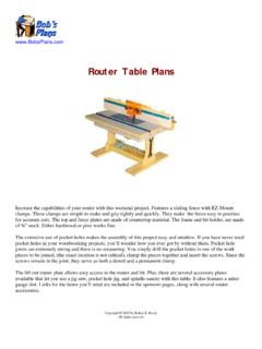
1 Garage Workbench Plans Every home woodworker knows the importance of making efficient use of the available space in his or her shop. This Workbench is designed to provide the maximum functionality using the minimum amount of space possible. It provides a work surface of about six feet by two feet and is about 35 in height. It s just the right size to provide ample work space for most projects. The features that make this Workbench ideal for the home shop are the built in clamping system, the nine drawers, the center cabinet space, and the mobility. The four inch casters enable you to easily roll it into position when needed and roll it aside when it is not in use. The top surface is made of two layers of 3/4 MDF. This provides an extremely flat and solid work surface. The T-track inlaid in the top and around the edges provides a versatile clamping system that easily clamps very small or very large work pieces.
2 Copyright 2006 by Robert E. Reedy All Rights Reserved This document may not be reproduced in whole or in part without the express written consent of the author. Table of Contents 1 Dimensions Drawings Materials List 1 .. x Materials List 2 .. xi Cutout Drawings Base/Back .. xii Cutout Drawings Top .. xiii Cutout Drawings Panels .. xiv Cutout Drawings Misc .. xv End and Center Panels .. 1 Base Dimensions & Layout .. 2 Back Dimensions & Layout .. 3 Top Dimensions & Layout .. 4 Sub Top Dimensions & Layout .. 5 Top Trim and T-Track ..6 Drawer Slides, Stiffener, Misc. Small Parts ..7 Drawer Fronts, Front Trim, and Doors .. 8 Drawer Boxes Dimensions .. 9 Middle Shelf .. 10 Table of Contents 2 Assembly Instructions Drawer Slides - Left Section - Left Panel ..11 Drawer Slides - Left Section - Right Panel.
3 12 Drawer Slides - Center Section - Left .. 13 Drawer Slides - Center Section -Right Panel ..14 Drawer Slides - Right Section - Left Panel .. 15 Drawer Slides - Right Section - Right Panel .. 16 Base to Panels .. 17 Stiffener - Casters ..18 Attach the Back ..19 Assemble the Face Frame .. 23 Attach the Middle Shelf .. 20 Assemble the Face Frame .. 21 Attach the Face Frame .. 22 Attach the Leveling Blocks to the Panels ..23 Attach the Front & Rear Leveling Blocks ..24 Attach the Sub Top .. 25 Attach the Inner Trim .. 26 Attach the Middle Trim .. 27 Attach the Top .. 28 Attach the Track to the Top ..29 Attach the Track to the Front & Ends ..30 Attach the Lower Trim ..31 Assemble the Drawer Boxes & Fronts .. 32 Attach Cabinet Doors .. 33 Attach Middle Door trim .. 34 Clamping System Parts .. 35 Assemble the EZ Mount Stop.
4 36 Clamping System Usage Instructions ..37 Clamping System Illustrations ..38 Clamping Long Work Pieces .. 39 40 Materials List - 1 Qty Size Material Item name 2 29 1/4 by 19 3/4 Oak Plywood End Panels 2 28 1/4 by 18 1/4 3/4 Plywood Middle Panels 1 66 1/2 by 19 3/4 Plywood Base 1 66 1/2 by 28 1/4 3/4 Plywood Back 1 72 by 24 3/4 MDF Board Top 1 68 by 19 3/4 3/4 MDF Board Sub Top 2 69 1/2 by 1 1/2 3/4 Wood or Plywood 1st Front & Back Sub Top Trim 2 21 1/4 by 1 1/2 3/4 Wood or Plywood 1st End Sub Top Trim 2 71 by 1 1/2 3/4 Wood or Plywood 2nd Front & Back Sub Top Trim 2 22 3/4 by 1 1/2 3/4 Wood or Plywood 2nd End Sub Top Trim 2 36 1/2 by 3/4 T-Track Front T-Track 5 24 1/2 by 3/4 T-Track End & Top T-Track 1 72 by 3/4 by 1/2 1/2 Thick MDF or Wood Front Lower T-Track Trim 2 24 by 3/4 by 1/2 1/2 Thick MDF or Wood End Lower T-Track Trim 17 18 1/4 by 1 1/2 3/4 Wood
5 Drawer Supports 5 6 by 1 1/2 3/4 Wood Small Drawer Supports 10 18 1/4 by 2 1/2 3/4 Wood Drawer Side Guides 4 18 1/4 by 3 3/4 Wood Lower Drawer Side Guides 6 18 1/4 by 2 3/4 Wood Lower Drawer Supports 2 14 1/2 by 2 3/4 Wood Lower Back Supports 1 27 1/2 by 2 3/4 Wood Center Lower Back Support 4 17 1/2 by 1 1/2 3/4 Wood 17 1/2 Leveling Block 4 16 3/4 by 1 1/2 3/4 Wood 16 3/4 Leveling Block 2 30 by 1 1/2 3/4 Wood 30 Leveling Block 1 66 1/2 2 by 4 (3 1/2 by 1 1/2 ) Stiffener 6 16 by 1 1/2 3/4 thick wood or plywood Drawer Trim 2 29 1/4 by 1 1/2 3/4 thick wood or plywood Vertical End Trim x Materials List - 2 QtySizeMaterialItem name230 by 1 1/2 3/4 thick wood or plywoodEnd Trim223 1/4 by 1 1/2 3/4 thick wood or plywoodVertical Divider Trim265 by 3 3/4 thick wood or plywoodUpper & Lower Trim13 1/2 by 30 1/2 3/4 thick wood or plywoodCenter Drawer Front23 1/2 by 16 1/2 3/4 thick wood or plywoodTop Drawer Front24 1/2 by 16 1/2 3/4 thick wood or plywood4 1/2 Drawer Front25 1/4 by 16 1/2 3/4 thick wood or plywood5 1/4 Drawer Front27 by 16 1/2 3/4 thick wood or plywood7 Drawer Front219 by 14 3/4 3/4 thick wood or plywoodCabinet Doors13/4 thick wood or plywoodDoor Lip619 by 2 7/8 3/4 thick wood or plywoodTop Drawer Sides419 by 3 7/8 3/4
6 Thick wood or plywood3 7/8 Drawer Sides419 by 4 7/8 3/4 thick wood or plywood4 7/8 Drawer Sides419 by 6 5/8 3/4 thick wood or plywood6 5/8 Drawer Sides228 3/8 by 2 7/8 3/4 thick wood or plywoodCenter Drawer Ends414 3/8 by 2 7/8 3/4 thick wood or plywoodTop Drawer Ends414 3/8 by 3 7/8 3/4 thick wood or plywood3 7/8 Drawer Ends414 3/8 by 4 7/8 3/4 thick wood or plywood4 7/8 Drawer Ends414 3/8 by 6 5/8 3/4 thick wood or plywood6 5/8 Drawer Ends129 1/8 by 18 1/4 1/4 HardboardCenter Drawer Bottom615 1/8 by 18 1/4 1/4 HardboardDrawer Bottom118 1/4 by 30 3/4 plywoodMiddle ShelfxiRev 9/14/20103/4" MDF or plywood Ci/66 1/2" Back 66 1/2" /i 12/utout Drawngs -BaseBack Base 66 12" xi48" 96" 9" 8 14" Cutout Drawings -Top 1st Front & Back Sub Top Trim 3/" 72" 3/48" 96" 19 4" 68" Sub Top 24 Top 4" MDF xiiiMills Millsdde Panedde PaneDrawer Trim (6) Drawer Trim (6) Drawer Trim (6) Drawer Trim (6) Cabinet Doors (2) Drawer Trim (6) Drawer Trim (6) xivEnd Panel 1st End Sub Top Trim 1st End Sub Top Trim Vertical End Trim (2) End Panel 30" Leveling Blocks (2) 2nd End Sub Top Trim 2nd End Sub Top Trim 30" Leveling Blocks (2) Vertical End Trim (2) 2nd Front & Back Sub Top Trim 2nd Front & Back Sub Top Trim Cabinet Doors (2) (1)Center Drawer Front Middle Trim (1) Vertical Divider Trim (2) Vertical Divider Trim (2) (1) 3/lCenter Lower Back Supports 4" by 4' by 8' pywood Cutout Drawings -Panels i(i/iialill w) 66 1/2" Stffener Make the stffener from 1 12" thck mater-A 2 BY 4 work3/4" thick material 96" Drawer Side Guides (10) Drawer Side Guides (10) Drawer Side Guides (10) Drawer Side Guides (10)
7 Drawer Side Guides (10) Drawer Side Guides (10) Drawer Side Guides (10) Drawer Side Guides (10) Drawer Side Guides (10) Drawer Side Guides (10) (6) (6) (6) (6) (6)Lower Drawer Supports Lower Drawer Supports Lower Drawer Supports Lower Drawer Supports Lower Drawer Supports 3/4" thick material 67 1/2" Lower Drawer Supports (6) (6)Lower Drawer Supports Lower Back Supports (2) Lower Back Supports (2) 17 1/2" Leveling Blocks (4) 17 1/2" Leveling Blocks (4) 16 3/4" Leveling Blocks (3) 17 1/2" Leveling Blocks (4) 17 1/2" Leveling Blocks (4) 16 3/4" Leveling Blocks (3) 16 3/4" Leveling Blocks (3) This board should provide enough extra wood to make the parts for the clamping system. Cutout Drawings -Misc 3 1/2" 7 1/2"7 1/2" xvEnd and Center Panels Page 1 2/4" /Mills (i) /el (i) 8 118 14" dde Pane2 Requred29 14" 19" End Pan2 RequredThe two end panels are 1" taller than the center panels.
8 This is because the center panels sit on the top surface of the base and the end panels extend 1/4" below the bottom surface of the The end panels are also 3/4" wider than the center panels. This is so they will be flush with the ends of the back section. C 2006 by Robert E. Reedy, Vandalia, OhioCopyright Base Dimensions & Layout Page 2 ///3/2"3/10" 9 1/4" 10"9 1/4"9 1/4"3/8" 18 " 2" 66 1/2" 9 12" 9 12" 18 58" 19" 2"2" 8" 8" 9 1/4" 5/8 Base Cut the base from 3/4" material, then drill and countersink holes for #8 screws as shown in the drawing above. All the screws around the edge are 3/8" from the edge. Copyright C2006 by Robert E. Reedy, Vandalia, OhioBack Dimensions & Layout Page 3 1/2"3/4"1/2" /3///4" /Back 17 30 17 1 14" 4" 10" 17 18" 22" 28 166 12" Cut the back from 3/4" material, then drill and countersink holes for #8 screws as shown in the drawing above.
9 Copyright C2006 by Robert E. Reedy, Vandalia, OhioTop Dimensions and Layout Page 4 27Fe 3/n 2T-Track & Miter Slot Cutout DimensionsT- Track Slot Td . t e s s d t s 3////g 4" 2" irst, cut the top from a piecof 4" MDF. Thecut the T-Track slots according to the drawing to the right. 4" he T-Track slot dimensions are baseon the center of the slotsHowever, the exaclocation of thesitemis strictly a matter of personal choice. T-Track sizevary from branto brand. The moscommon sizeare 4" wide by 12" deep or 34" wide by 38" deep. Cut the slots so the track you're usinis flush with the top surface. 24" 6" CopyriCght2006 by Robert E. Reedy, Vandalia, Ohio Sub Top Dimensions and Layout Page 5 Sub Top 68" Drill and counter screwholes for #8 flathead screws in the locations shown below. 1//8" /8" /8" lle //1/8" 1/8" 10" 3" 3" 0" 3" 3" 3" 3" 1 18" 1 11 11 1 Sub Top Screw Hoe Layout Screw HoLayout 19 38" 19 38" 4 54 5/19 12" 6" 26" 1/26" 6" 9 12" 19 3/4" C 2006 by Robert E.
10 Reedy, Vandalia, OhioCopyright Top Trim &T-Track Page 6 The Sub Top trim is made of 3/4" thick by 1 1/2" high material. This because the T-Track is 1/2" by 3/4". /rim (i) 1 1/45 69 12" 45 1st Front & Back Sub Top T2 Requred2" 45 45 im ired/im (i) 1 1/1 1/im (id) /1 1/r() 45 21 14" 1st End Sub Top Tr2 Requred2" 45 71" 2nd Front & Back Sub Top Tr2 Requre45 22 34" 2" 2nd End Sub Top T2 Requ45 2"If you have a pocket hole jig, I reccommend drilling pocket holes in the 2nd Sub Top Trim pieces as shown. These pocket holes will be used to secure the Top to the Sub Top. The exact location of the pocket holes is not critical. The important thing is that they do not line up with the screw holes in your T-Track. If you do not have a pocket hole jig, the Top can be secured with finishing nails or glue. Front T-Track (2 Required) End T-Track (2 Required) /2" 23 1/4"35 1 The T-Track trim is made of 1/2" thick by 3/4" high material.