Transcription of Broken Arch Mantel Clock Plans - BobsPlans.com
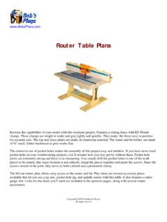
1 Broken Arch Mantel Clock Plans This stately Mantel Clock is reminiscent of the Broken Arch clocks made in Connecticut after the Revolutionary War. The simple lines of this flat capped Broken arch style are less ornate than the scroll or swan's neck designs but it's beauty has withstood the test of time. This is really an easy project to make. Designed for the woodworker with basic woodworking skills, it requires a table saw, scroll saw, router, drill press, and dowel jig. The Broken arch pediment and the base trim are the only parts that require scroll cuts.
2 The Clock pictured is made of solid cherry with a medium walnut stain. The chiming quartz pendulum movement, brass finial, and brass dial, and other hardware is readily available. Sources for the necessary hardware are listed on the Materials List page. The finished Clock is about 21" high, 12" wide and 6" deep. the dial is 7 1/2" square. Copyright 2005 by Robert E. Reedy All rights reserved Broken Arch Mantel Clock Plans Table of Contents Materials List .. 1. Base Drawings .. 2. Base Trim Drawings.
3 3. Case Sides 4. Case Sides Hinge Location .. 5. Broken Arch Pediment .. 6. Crown Caps Drawings .. 7. Dial Frame Drawings .. 8. Door Parts Drawings .. 9. Back Cover Drawings .. 10. Base Assembly .. 11. Top Assembly .. 12. Case Assembly .. 13. Dial Frame Assembly .. 14. Door Assembly .. 15. Magnetic Catch Installation .. 16. Door Glass Installation .. 17. Door Installation .. 18. Dial Assembly Installation .. 19. Back Cover Installation .. 20. Broken Arch Pediment Full Size Pattern .. 21. Speaker Holes Pattern.
4 22. Copyright 2007 by Robert E. Reedy, Vandalia, Ohio All Rights Reserved Materials List Dial Frame Segment Dial Frame Segment Page 1. Front Base Trim Door Side Base Qty Item Length Width Thick Material 1 Base .. 11 4 Hardwood 1 Top .. 11 4 Hardwood 2 Sides .. 14 4 Hardwood 1 Broken Arch Pediment .. 11 3 Hardwood 2 Crown Caps .. 6 1 Hardwood Dial Frame Segment Dial Frame Segment 1 Finial Seat .. 1 1 1/8 Hardwood 2 Front & Rear Base Trim .. 12 3/4 1 Hardwood 2 End Base Trim .. 5 3/4 1 Hardwood 4 Dial Frame 9 1 Hardwood Rear Base Trim 2 Door Side.
5 14 1 Hardwood Side Door Side 2 Door Top & Bottom .. 9 1 Hardwood 1 Door Divider .. 8 1 Hardwood 2 Top & Bottom Glass Retainer .. 7 3/8 Hardwood Base End Trim Base End Trim 2 Middle Glass 7 5/16 3/8 Hardwood 2 Upper Side Glass Retainer .. 8 3/8 Hardwood 2 Lower Side Glass Retainer .. 4 3/8 Hardwood 2 Back Mounting Strip .. 9 Hardwood 1 Upper Door Glass .. 8 8 7/16 1/8 Single Strength Glass 1 Lower Door Glass .. 4 13/16 8 7/16 1/8 Single Strength Glass 1 Back 14 10 1/8 Hardboard 1 Dial Mounting 10 9 Hardboard Door Bottom Side Note: The door glass pieces should be 1/16 smaller than the openings in the door on each side.
6 I recommend you measure the openings after the door is 72". completed and then cut the glass accordingly. This allows for slight expansion and contraction of the wood. Qty Item Size Source Door Top 1 Brass Dial 7 By 7 Klockit (Stock No. 26878). 1 Clock Movement Klockit (Stock No. 12232). Bob Diameter: 2 , Pendulum Length: 8 . (Pendulum length is from center of dial to tip of pendulum). Top 1 Set of Hands (Black Serpentine)3 1/8 Klockit (Stock No. 67931). 1 Brass Finial 3 H x 1 3/8 Dia. Klockit (Stock No.)
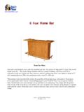
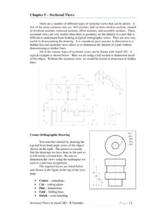
7 38128). Door Divider 1 Brass Door Knob 7/16 By 3/8 Klockit (Stock No. 39049). 1 Magnetic Catch 3/8 Klockit (Stock No. 39011). 1 Door Decal 1 By 4 Murray Clock Craft (Decal #5). Sources Broken Arch Pediment KLOCKIT MURRAY Clock CRAFT. The drawings to the right should help you determine how to efficiently cut the parts from 5 1/2" wide by 72" hardwood boards. The smaller parts are not pictured because they can be cut from smaller pieces you may have in your scrap bin. Cap Cap Copyright (c) 2007 by Robert E.
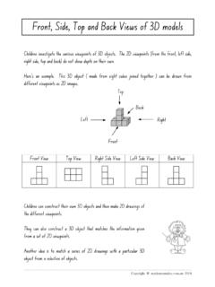
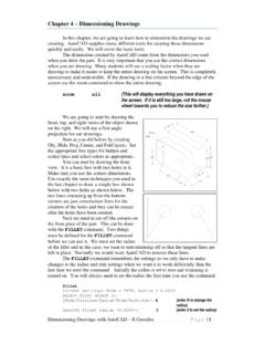
8 Reedy All Rights Reserved Base Drawings Page 2. 11 1/4". 1/2". 1/2". 3/8". Base 3/8". (Top View). 4 1/4". Drill four 3/16" diameter holes 3/8" from each end and 1/2". from the front and rear edges as shown. These holes are for the flathead screws that attach the sides to the bottom. These holes go completely through the wood and should be countersunk on the bottom for #8 screws. 3/16" Dia. 3/8" 3/8". 1/2". 1/2". 1". Base 1". (Top View). 3/8" 3/8". 1/4" Dia. Drill four 1/4" diameter dowel holes in the top.
9 They are 3/8" from each end and 1" from the front and rear edges as shown. These holes are for the 1/4" by 1" dowel pins that 3/8" align the sides to the bottom. These holes should be only 3/8". 1/2" deep. Front 1" 1". Next, drill three 1/4" diameter dowel holes in the front and rear edges. Then drill two 1/4" diameter dowel holes in each end as in the edge and end views shown below and to (End View). 3/8". the right. These holes are for the 1/4" by 1" dowel pins that align the trim to the bottom.
10 These holes should be 3/4" 1/2" 1/2". deep. (Edge View). 3/8". 1 1/2" 1 1/2". 5 5/8". Note: You will notice that the dowel holes for the end trim and the 3/16" screw holes through the top will intersect. This results in the dowel pins blocking the screw holes. Not a problem because the holes can be easily redrilled after the trim is attached. Copyright (c) 2007 by Robert E. Reedy All Rights Reserved Base Trim Drawings Page 3. 12 3/4". 45 45 . 3/4" (Top View) Front and Rear Trim (Two required). 11 1/4".