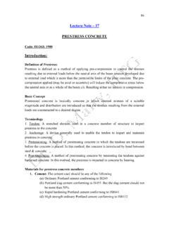
Transcription of Orthographic Projections - Indian Institute of Technology ...
1 Orthographic MauryaOrthographic Projections Orthographic Projections is a technical drawing in which different views of an object are projected on different reference planes observing perpendicular to respective reference plane. Different Reference planes are; Horizontal Plane (HP) Vertical Plane (VP) Side or Profile Plane (PP) Different views are; front view (FV) Projected on VP Top view (TV) Projected on HP Side view (SV) Projected on PPNOTATIONSF ollowing notations should be followed while namingDifferent views in Orthographic S front view a a b Same system of notations should be followed incase numbers, like 1, 2.
2 3 are POINT A LINE ABIT S TOP view a abIT S SIDE VIEWa a b TERMS ABOVE & BELOW WITH RESPECT TO AND TERMS INFRONT & BEHIND WITH RESPECT TO of viewsProjectionsConvergeParallelOrthogon alObliqueAxonometricMultiviewPictorial drawingPerspective drawingMulti- view drawingView comparisonPictorial drawingPerspective drawingMulti-viewdrawingDifficult to createEasy to and angle distortionObject looks morelike what our and shape distortionRight angle becomes obtuse hole becomes ellipseDistortedwidthAccurately presents object s details, and trainingto to Hp & to VpPLANESPRINCIPAL PLANESHP AND VPAUXILIARY PLANESA uxiliary Vertical Plane( )Profile Plane ( )Auxiliary Inclined Plane( )THIS IS A PICTORIAL SET-UP OF ALL THREE DIRECTION IS A NORMAL WAY OF OBSERVING THE IN THIS DIRECTION ONLY VP AND A view ON IT (FV)
3 CAN BE OTHER PLANES AND VIEWS ON THOSE CAN NOT BE IS ROTATED DOWNWARD 900 AND BROUGHT IN THE PLANE OF IS ROTATED IN RIGHT SIDE 900 ANDBROUGHT IN THE PLANE OF PATTERN OF PLANES & VIEWS OF Orthographic Projections DRAWN IN FIRST ANGLE METHOD OF PROJECTIONSLSVTVPROCEDURE TO SOLVE ABOVE PROBLEM:-TO MAKE THOSE PLANES ALSO VISIBLE FROM THE ARROW DIRECTION, A) HP IS ROTATED 900 DOUNWARD B) PP, 900IN RIGHT SIDE WAY BOTH PLANES ARE BROUGHT IN THE SAME PLANE CONTAINING VP. PATTERN OF PLANES & VIEWS (First Angle Method)Click to view AnimationOn clicking the button if a warning comes please click YES to continue, this program is safe for your systems1.
4 Firstangle system2. Thirdangle systemFirstquadrantThirdquadrant-Europea n countries-ISO standard-Canada, USA,Japan, ThailandTransparentplanesOpaqueplanes1st angle system(Opaque planes)3rdangle system(transparent planes/glass box) Orthographic viewsFoldinglineFoldinglineFoldinglineFo ldingline1stangle system3rdangle systemOrthographic views1stangle system3rdangle systemFront ViewFront ViewRight Side ViewRight Side ViewTop ViewTop ViewViews arrangementProjection symbols1stangle system3rdangle Natural Method: Revolve the object with respect to observerMethods of Orthogonal Projection2. Glass box method: The observer moves around the viewRight side viewTop viewRight sideviewTop viewplayplayFrontviewGlass box conceptGlass box : Revolution of the planes of projectionBottom viewLeft side viewRear viewHeightWidthDepthRelative orientation of viewsSummary : Problem solving steps1234 GivenSteps for Orthographic Views1.
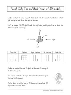
5 Select thenecessary views2. Layout theselected viewson a drawingsheet. 3. Complete eachselected Complete thedimensions and notes. 451521526425~40 FrontTopChoose a drawing scale(say 1:1)FrontTopyyxxxxyyzView selection procedures1. Orient the object to the bestposition relativetoa glass box. 2. Select the front Select adjacent : Orient the object1. The object should be placed in its natural !2. The Orthographic viewsshould represent the true sizeand trueshapeof an object (as much as possible).GOODS uggestions:Select the front view1. The longest dimension of an object should be presentedas a width (in a front view ).
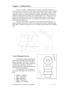
6 InappropriateFirst choiceGoodSecond choiceUse more space Inappropriate2. The adjacent views project from the selected front view should be appeared in a natural :Select the front view3. It has the fewestnumber of hidden :Select the front viewSuggestions:Select an adjacent viewInappropriateInappropriate1. Choose the view that has the fewest number of hidden Choose the minimumnumber of views that can represent the major features of the s information is placed on a separated :Select an adjacent viewAll information is placedon a single Choose the views that are suitable to a drawing :Select an adjacent viewPoorNot enough spacefor another adjacent orientation of theselected selection has 3 stepsOrientthe objectSelectfront viewSelectadjacent viewsObject that requires only one-viewFlat (thin) parthaving a uniform thickness such as a gasket, sheet metal views provide only apart s thickness !
7 1 !Infer from CLObject that requires only one-viewExampleExampleFlat (thin) parthaving a uniform thickness such as a gasket, sheet metal adjacent view !Object that requires only two-viewThe 3rdview has no significant contours of the object.(provides no additional information)ExampleObject that requires only two-viewIdentical view 1 The 3rdview has nosignificant contours of the object.(provides no additional information)Object that requires only two-viewIdentical view 2 The 3rdview has no significant contours of the object.(provides no additional information)Example-1 Identify surfaces perpendicular or inclined to the view Surfaces parallel to the view would not be visible in that view .
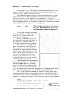
8 First draw horizontal and vertical reference planes (easily identifiable on drawing) Start drawing from the reference to draw projectionsTop viewHorizontal reference plane (HP)Vertical reference plane (VP)HPVPF ront viewSide viewTop view80+40+80=2005070 5030+20=50 Midpoint3580407020200 505080407020 front viewSide viewTop view807012550252025+xyFRONT VIEWTOP VIEWFOR PRESENTATION IS GIVENDRAW THREE VIEWS OF THIS OBJECTBY FIRST ANGLE projection METHODORTHOGRAPHIC PROJECTIONSE xample-2 FOR PROJECTIONSFRONT VIEWTOP VIEWXYPICTORIAL PRESENTATION IS GIVENDRAW THREE VIEWS OF THIS OBJECTBY FIRST ANGLE projection METHODE xample-3 FOR PROJECTIONSFRONT VIEWTOP VIEWXYPICTORIAL PRESENTATION IS GIVENDRAW THREE VIEWS OF THIS OBJECTBY FIRST ANGLE projection METHODE xample-4 front VIEWTOP VIEWXYFOR
9 PROJECTIONSPICTORIAL PRESENTATION IS GIVENDRAW THREE VIEWS OF THIS OBJECTBY FIRST ANGLE projection METHODE xample-5 FOR PROJECTIONSFRONT VIEWTOP VIEWXYPICTORIAL PRESENTATION IS GIVENDRAW THREE VIEWS OF THIS OBJECTBY FIRST ANGLE projection METHODE xample-6 Example-7xyFV353510TV3020104070 OFOR PRESENTATION IS GIVENDRAW FV AND TV OF THIS OBJECTBY FIRST ANGLE projection METHODORTHOGRAPHIC PROJECTIONSE xample-8 SVTVyxFV303010301030 ALL VIEWS IDENTICALFOR PRESENTATION IS GIVENDRAW THREE VIEWS OF THIS OBJECTBY FIRST ANGLE projection METHOD14 Orthographic PROJECTIONSxyFVSVE xample-9TV1040606040 ALL VIEWS IDENTICALFOR PRESENTATION IS GIVENDRAW THREE VIEWS OF THIS OBJECTBY FIRST ANGLE projection METHOD15 Orthographic PROJECTIONSFOR PRESENTATION IS GIVENDRAW THREE VIEWS OF THIS OBJECTBY FIRST ANGLE projection METHODORTHOGRAPHIC PROJECTIONSxyFVSVALL VIEWS IDENTICAL4060604010 TOP VIEWE xample-10O20 D30 D60 PRESENTATION IS GIVENDRAW FV AND TV OF THIS OBJECTBY FIRST ANGLE projection METHODORTHOGRAPHIC PROJECTIONSTOP VIEWE xample-11450 XFVY3040TV30 D404015 OFOR PRESENTATION IS GIVENDRAW FV AND TV OF THIS OBJECTBY FIRST ANGLE projection METHODORTHOGRAPHIC PROJECTIONSE xample-12
10 LSVY25251050 FVX101015 OPICTORIAL PRESENTATION IS GIVENDRAW FV AND LSV OF THIS OBJECTBY FIRST ANGLE projection METHODORTHOGRAPHIC PROJECTIONSE xample-13 FOR PRESENTATION IS GIVENDRAW THREE VIEWS OF THIS OBJECTBY FIRST ANGLE projection METHODORTHOGRAPHIC PROJECTIONSFRONT VIEWTOP VIEWXYE xample-14