Transcription of General Model DY Specifications Model DYA Vortex …
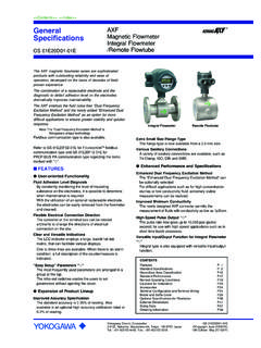
1 GeneralSpecifications<<Contents>> <<Index>>GS 01F06A00-01 ENModel DYModel DYAV ortex FlowmeterYokogawa Electric Corporation2-9-32, Nakacho, Musashino-shi, Tokyo, 180-8750 JapanTel.: 81-422-52-4443 Fax.: 81-422-52-2018GS 01F06A00-01EN Copyright Dec. 200017th Edition Feb. 2012 Based on the field proven technologydigitalYEWFLO, combines the field proven sensor andbody assembly used in more than 300,000 unitsinstalled worldwide, with an unique digital electronicsincluding SSP (Spectral signal processing)* provides high accuracy and stability,even in harsh process conditions. Combined with highreliability and robust design, it delivers improvements inplant efficiency and reduced operating Multi-Variable Type (OPTION:/MV)build in temperature sensor, so that temperaturemeasurement and Mass Flow calculation is Reduced Bore Type (OPTION:/R1, /R2)Integrated and casting construction with concentricreduced bore benefits piping cost reduction and lower flow range.
2 * SSP is YOKOGAWA s original technology for digital signal processing. FEATURES New functions with SSP (Spectral SignalProcessing) technology :SSP is built into the powerful electronics ofdigitalYEWFLO. SSP analyses the fluid conditionsinside digitalYEWFLO and uses the data toautomatically select the optimum adjustment for theapplication, providing features never beforerealized in a Vortex accurately senses vortices in the low flowrange, providing outstanding flow stability. Advanced Self-diagnostics :The application condition, such as high pipelinevibration and abnormal flow, is predicted andindicated. High Accuracy : of Reading (Liquid)( of Reading : Typical Accuracy/ Non-Guaranteed) 1% of Reading (Gas, Steam) Wide Process Temperature Range : High temperature version up to 450 C Cryogenic version minimum 196 C Simple Parameter settings :Frequently-used selections grouped together in aquick-access format decreases commissioning time.
3 Clear, Concise Indicator :Simultaneous flow rate or temperature (Option) andtotal flow rate along with process diagnosisconveniently displayed. Dual output for Analog / Pulse:Simultaneous output for flow rate or temperature(Option) and pulse. Alarm output, Status output (Flow switch)An alarm signal output, in case alarm occurs. No moving parts stainless steel detector : Highdurable and safety. Remote cable length 30m maximum. Explosion proof construction, JIS / FM / CENELECATEX (KEMA) / CSA / SAA (Explosion proof /Intrinsically safe). Communication function includes FOUNDATIONTM*1fieldbus, BRAIN and HART*2 to GS01F06F01-01E for Fieldbuscommunication type marked with .*1 FOUNDATION is a registered trade mark ofFOUNDATION Fieldbus.*2 HART is a registered trade mark of the HARTC ommunication DY-NRemote Type DetectorModel DYAR emote Type ConverterModel DY-D,DY-EIntegral TypeModel DY/R1, DY/R2 Reduced Bore TypeContentsFeaturesP.
4 1 Standard SpecificationsP. 2 Model and Suffix CodesP. 5 Option SpecificationsP. 8 Option Multi-Variable TypeP. 11 Option Reduced Bore TypeP. 12 SizingP. 13 Option Specifications (For Explosion Protected type)P. 18 Remarks on InstallationP. 21 External DimensionsP. 24 Operating InstructionsP. 432 All Rights Reserved. Copyright 2000, Yokogawa Electric Corporation<<Contents>> <<Index>>GS 01F06A00-01EN 17th Edition Feb. 10, 2012-00[MULTI-VARIABLE TYPE] (OPTION)digtalYEWFLO build in temperature sensor (Pt1000) inthe Vortex shedder measuremt and Mass Flow Calculation bytemperature is available. (Refer to ) digitalYEWFLO build in steam trend, and Massmeasurement of saturated steam and super heatsteam (Mass Flow Calculation) Accuracy of digtalYEWFLO Multi-Variable type is of rate for temperature measurement, 2% ofrate for Mass Flow Calculation (saturated steam).[REDUCED BORE TYPE] (OPTION)Integrated and casting construction with concentricreduced bore piping makes ; Cost reduction and safety improvement: expand lowflowrate region Replace work and cost reduction: the same face-to-face dimension with standard type.
5 STANDARD SPECIFICATIONSP erformance SpecificationsFluid to be Measured :Liquid, Gas, Steam (Avoid Multiphase Flowand Sticky Fluids)Measuring Flow Rates :Refer to Table 6 Accuracy : of Reading (Liquid) 1% of Reading (Gas, Steam)Refer to Multi-Variable Type is selected,refer to : of ReadingCalibration :This flowmeter is factory-calibrated using awater and flow calibration by waterflow when Multi-Variable Type is Operating ConditionProcess Temperature Range : 29 to 250 C ( General ) 196 to 100 C (Cryogenic Version:option) 29 to 450 C(High Process TemperatureVersion:option)When Multi-Variable Type is selected, referto to Figure 1 for integral converter Pressure Limit : ( 1 kg/cm2) to flange Temperature Range : 29 to 85 C ( Remote type detector) 40 to 85 C (Remote type converter) 29 to 85 C (Integral type, refer to Figure 1) 29 to 80 C ( Integral type with Indicator,refer to Figure 1) 30 to 80 C ( Remote type converter withIndicator)Ambient Humidity :5 to 100% RH (at 40 C)(No Condensation)Power Supply Voltage ( ): to 42 V DC(Refer to Figure 2 ; Relationship BetweenPower Supply Voltage and Load Resistance)Mechanical SpecificationsMaterial ( General Type):Refer to Parts:Body; Stainless steel JIS SCS14A,ASTM CF8 MShedder Bar; Duplex stainless steel[equivalent to JIS SUS329J1]Size 15mm ASTM S31803 Size 25mm to 300mm DCS1*1,EN *1 DCS1 is a registered trademark of Daido CastingsCo.
6 , : JIS SUS316 stainless steel withpolytetrafluoroethylene (Teflon) Parts:Housing (Case, Cover):Aluminum alloy JIS ADC12 Name Plate: Stainless steel JIS SUS304 DYA Mounting Bracket for 2B pipe:Cold-reduced carbon steel sheet JIS SPCC,JIS SECCC oating Color:Housing:Polyurethane corrosion-resistant coatingDeep sea moss green (Munsell )DYA Mounting Bracket for 2B pipe:Polyurethane corrosion-resistant coatingFrosty white (Munsell )Degree of Protection:IP67, NEMA4X, JIS C0920 watertight Area Classifications:Refer to item Option Specifications Electrical Connection:JIS G1/2 female, ANSI 1/2 NPT female,ISO M20 femaleSignal Cable: Model DYC cable, used for remote detector length : 30 Sheath Material: Heat resisting polyethyleneDurable Temperature : 40 to 150 CWeight:Refer to item External Dimensions .Mounting:Integral type and Remote type detector :Flange mounting or wafer mounting byflange adjacent to the type converter : 2 inch pipe SpecificationsNote*: Pulse output,alarm output and status output usethe common terminal, therefore these functionsare not used Signal ( ): Dual Output (Both Analog andTransistor contact output can be obtainedsimultaneously).
7 In this case refer to the item3<<Contents>> <<Index>>All Rights Reserved. Copyright 2000, Yokogawa Electric CorporationGS 01F06A00-01EN 17th Edition Feb. 10, 2012-00 Remarks on installation for power supplyand pulse output : 4 to 20 mA DC, 2-wire Contact Output* :Open collector, 3-wire ,alarm,status output are selected byparameter rating: to 30 V DC, 120 mA DCLow level: 0 to 2 V DC. (refer to Figure3)Communication Requirements :Communication Signal :BRAIN or HART communication signal(superimposed on a 4 to 20 mA DCsignal)Note: HART is a registered trademark of the HARTC ommunication of Communication Line :Load Resistance :250 to 600 (including cable resistance).Refer to Figure Voltage to 42 V DC for digital communicationsBRAIN and HART protocols .( to 30 VDC for intrinsically safe type).Refer to Figure :Space from other Power Line: 15cm ormore (Parallel wiring should be avoided.)Communication Distance :Up to 2 km,when polyethylene insulatedPVC-sheathed cables (CEV cables) distance variesdepending on type of cable used and Capacitance: F or lessLoad Inductance: mH or lessInput Impedance Communicating Device:10 k or more at Protocol RevisionHART protocol revision can be selected from5 or 7 when ordering.
8 ( -J only)The protocol revision can be changed byuser : Protocol revision supported by HART configura-tion tool must be the same or higher than that ofthe o r DYA HART 5DY o r DYA HART 7 Protocol revision supported by HART configuration toolAvailableNot AvailableAvailableAvailable57 Functions:Damping Time Constant :0 to 99 Sec (63% response time)Note: Delay time is output circuit time constant is Output Function*:Pulse output is selected from scaled pulse,unscaled pulse, frequency (number of pulsesoutput per second at 100% of output).Pulse frequency : Max 10 kHzDuty cycles : (1:2 to 2:1)Self-diagnostics and Alarm Output *:In case alarm (over range output signal,EEPROM error, vibration noise, abnormalflow such as clogging, bubble) occurs, analarm signal is output and alarm signal output goes fromclose(ON) to open(OFF) during Output Function:Analog output is selected from flowrate andtemperature value when option code /MV Output Function *:Flow Switch:In case flow rate decreases under the flowset value,a status signal is signal output mode can reverse (ON/OFF).
9 Data Security During Power Failure:Data (parameter, totalizer value, etc) storageby EEPROM. No back-up battery :Instrument Error Correction: Vortex flowmeter instrument errors can becorrected by segment Number Correction:Output error at Reynolds number 20000 orless is corrected by using five-break-pointline-segment Expansion Correction:When measuring a compressibility gas andsteam, this expansion factor is useful to correctthe error at high velocity of flow (35m/s or more).Down-scale or Up-scale burn case a CPU or EEPROM failure occurs,flow meter output the signal of Up-scale( mA or more).Up-scale or Down-scale ( mA or less) isuser-selectable through the fail mode :Flow rate (% or engineering units) ortemperature value and totalizer can beindicated message for self diagnostics parameter setting can be operated bykey mounting direction, the right and left 90 Conformity Standards:EN61326-1 Class A, Table 2 (For use inindustrial locations), EN61326-2-3EN55011 Class A Group 1 Note1: This instrument is a Class A product, and it isdesigned for use in the industrial use this instrument in the industrial environ-ment : Use the metal conduit for the remote Equipment Directive:Notified Body Identification Number 0038 Module H4 All Rights Reserved.
10 Copyright 2000, Yokogawa Electric Corporation<<Contents>> <<Index>>GS 01F06A00-01EN 17th Edition Feb. 10, 0 1 5 III12600 IIIIII30042 IIDY 3 0 0 Article 3,**Paragraph 3 IIIIIIIIIDY050PS(MPa)*DY025 MODELDN(mm)*CATEGORY**PS-DN(MPa-mm)DY250 DY 1 0 0DY040DY 2 0 0DY 1 5 0 Article 3,**Paragraph 3DY080* PS: Maximum allowable pressure for Flow tube, DN: Nominal size** Refered to Table 6 coverd by ANNEX II of EC Directiveon Pressure Equipment Directive 97/23/EC** DY015 and DY025 are not regulated by Temperature ( C)With IndicatorAmbient Temperature ( C)Without Indicator85-5025085-298080DY F F ig-0155 Figure 1 Ambient Temperature limit (Integal Type) R=E - Supply Voltage E(V)( )Communicationapplicable rangeBRAIN or HART30 Load Resistance DYF Fig-02 Figure 2 Relationship Between Power Supply and LoadResistanceHIGH levelLOW level0 V0 to 2 VDYF Fig-03 Figure 3 High and low level (Pulse output)5<<Contents>> <<Index>>All Rights Reserved.