Transcription of General Model EJA530A/HAC Specifications (High Accuracy Type)
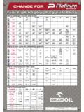
1 GeneralSpecifications<<Contents>> <<Index>>The gauge pressure transmitter Model eja530a /HACcan be used to measure liquid, gas, or steampressure. Both output a 4 to 20 mA DC signalcorresponding to the measured pressure, and alsofeature remote setup and monitoring through commu-nications with the BRAIN terminal and CENTUMCS or XL or HART 275 host. STANDARD SPECIFICATIONSR efer to GS 01C22T02-00E for Fieldbuscommunication type marked with . PERFORMANCE SPECIFICATIONSZero-based calibrated span, linear output, wettedparts material code S and silicone Accuracy of Calibrated Span(including the effects of zero-based linearity, hyster-esis, and repeatability) % of Span, (A, B and C capsule) % of Span, (D capsule)For spans below X, [ ] % of span, (A, B and C capsule) [ ] % of span, (D capsule)XSpanXSpanWhere X equals:CapsuleX MPa {psi}A40 kPa { } {29}C1 {145}D8 {1160}Ambient Temperature EffectsTotal Effects per 28 C (50 F) Change [ Span URL]Stability of URL per 12 monthsVibration Effects % of URL(5 to 15Hz; 4mm peak-to-peak constant displace-ment, 15 to 150Hz; 2g, 150 to 2000Hz; 1g)Power Supply Effects % per Volt (from to 32 V DC, 350 ) Model eja530a /HACG auge Pressure Transmitter (High Accuracy Type) Yokogawa Electric Corporation2-9-32, Nakacho, Musashino-shi, Tokyo, 180-8750 JapanPhone: 81-422-52-5690 Fax.
2 : 81-422-52-2018GS 01C21F01-02 EGS 01C21F01-02E Copyright Apr. 20025th Edition Apr. 2003 FUNCTIONAL SPECIFICATIONSSpan & Range LimitsABMeasurementSpan and RangeSpanRangeSpanRangepsi (/D1) to 290 to to 2900 to 290bar (/D3) to 2 kgf/cm2(/D4) to 20 to 21 to 200 to 200 to 21 to 200 to 20 MPa10 to 200kPa0 to to 20 to to to 100 to 10 CSpanRange0 to 14505 to 1000 to 1005 to 1000 to 100720 to 72005 to 500 to 50 DSpanRange0 to 720050 to 5000 to 50050 to 5000 to is defined as the Upper Range Limit from thetable Adjustment LimitsZero can be fully elevated or suppressed, within theLower and Upper Range Limits of the Zero Adjustment External zero is continuously adjustable with %incremental resolution of span. Span may beadjusted locally using the digital indicator with Position EffectRotation in diaphragm plane has no effect. Tilting upto 90 will cause zero shift up to kPa { inH2O}which can be corrected by the zero Two wire 4 to 20 mA DC output with digital communi-cations.
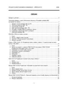
3 BRAIN or HART FSK protocol are superim-posed on the 4 to 20 mA AlarmOutput status at CPU failure and hardware error;Up-scale:110%, mA DC or more (standard)Down-scale: -5%, mA DC or lessNote : Applicable for Output signal code D and E.[Style: S2]2 All Rights Reserved. Copyright 2002, Yokogawa Electric Corporation<<Contents>> <<Index>>Damping Time Constant (1st order)The sum of the amplifier and capsule damping timeconstant must be used for the overall time damping time constant is adjustable from to64 Constant (approx. sec) , B, C, and DCapsule (Silicone Oil)Ambient Temperature Limits (approval codes may affect limits)-40 to 85 C (-40 to 185 F)-30 to 80 C (-22 to 176 F) with LCD DisplayProcess Temperature Limits(approval codes may affect limits)-40 to 120 C (-40 to 248 F)Ambient Humidity Limits5 to 100 % RH @ 40 C (104 F)Maximum OverpressureA4 MPa {580 psig}B4 MPa {580 psig}C20 MPa {2900 psig}D60 MPa {8500 psig}PressureCapsule Working Pressure Limits (Silicone Oil)Maximum Pressure LimitA200 kPa {29 psig}B2 MPa {290 psig}C10 MPa {1450 psig}D50 MPa {7200 psig}PressureCapsule Supply & Load Requirements(Safety approvals can affect electrical require-ments, see graph below)With 24 V DC supply, up to a 570 load can beused.
4 ( )Power supply voltage E (V DC) 1. Relationship Between Power Supply Voltageand External Load ResistanceSupply Voltage to 42 V DC for General use and flameproof to 32 V DC for lightning protector (Optionalcode /A) to 30 V DC for intrinsically safe, Type n,nonincendive, or non-sparking typeMinimum voltage limited at V DC for digitalcommunications, BRAIN and HARTLoad (Output signal code D and E)0 to 1335 for operation250 to 600 for digital communicationEMC Conformity Standards: , EN61326, AS/NZS 2064 European Pressure Equipment Directive 97/23/ECCategory III, Module H, Type of Equipment: PressureAccessory-Vessel, Type of Fluid: Liquid and Gas,Group of Fluid: 1 and 2 Communication Requirements BRAINC ommunication DistanceUp to 2 km ( miles) when using CEV polyethyl-ene-insulated PVC-sheathed cables. Communicationdistance varies depending on type of cable F or less (see note)Load mH or less (see note)Input Impedance of communicating device10 k or more at : For General -use and Flameproof Intrinsically safe type, please refer to OPTIONAL Specifications .
5 HARTC ommunication DistanceUp to km (1 mile) when using multiple twisted paircables. Communication distance varies depending ontype of cable the following formula to determine cable lengthfor specific applications:L=-65 x 106(R x C)(Cf + 10,000)CWhere:L = length in meters or feetR = resistance in (including barrier resistance)C = cable capacitance in pF/m or pF/ftCf = maximum shunt capacitance of receiving devicesin pF/m or pF/ftGS 01C21F01-02E Oct. 01, 2002-003<<Contents>> <<Index>>All Rights Reserved. Copyright 2002, Yokogawa Electric Corporation PHYSICAL SPECIFICATIONSW etted Parts Materials:Diaphragm and Process connectorRefer to Model AND SUFFIX CODE. Non-wetted Parts Materials:HousingLow copper cast-aluminum alloy with polyurethanepaint (Munsell )Degrees of ProtectionIP67, NEMA4X, JIS C0920 immersion proofCover O-ringsBuna-NData plate and tagSUS304 Fill FluidSilicone, Fluorinated oil (option) kg ( lb) without integral indicator, to the Model code to specify the process andthe electrical connection type.
6 < Settings When Shipped > Selected from mmH2O, mmAq, mmWG, mmHg, Torr, Pa, hPa, kPa, MPa, mbar, bar, gf/cm2, kgf/cm2, inH2O, inHg, ftH2O, psi, or atm.(Only one unit can be specified)Tag NumberOutput ModeDisplay ModeOperation ModeDamping TimeConstantAs specified in order *1 Linear 2 sec. Normal unless otherwise specified in order Linear Calibration Range UnitsAs specified in orderAs specified in orderCalibration RangeHigher Range ValueCalibration RangeLower Range *1:Up to 16 alphanumeric characters (including -and ) for Output Signal code D or up to 8alphanumeric characters for Output Signal codeE will be entered in the amplifier 01C21F01-02E Oct. 01, 2002-004 All Rights Reserved. Copyright 2002, Yokogawa Electric Corporation<<Contents>> <<Index>> Model AND SUFFIX CODES Model eja530a .. -D .. -E .. -F .. A ..B .. C .. D .. S ..H .. 4 ..7 ..8 ..9 ..N ..-0 ..0 .. 2 .. 3 .. 4 ..5 ..7 ..8 ..9 ..D .. E .. N .. E ..F ..N .. ModelDescription EJA530 AOutput SignalMeasurement span (capsule)Wetted parts materialProcess connectionElectrical connectionIntegral indicatorMounting bracketHigh accuracyOptional codesGauge pressure transmitter4 to 20 mA DC with digital communication (BRAIN protocol)4 to 20 mA DC with digital communication (HART protocol, refer to GS 01C22T01-00E) Digital communication (FOUNDATION Fieldbus protocol, refer to GS 01C22T02-00E)
7 10 to 200 kPa{ to 2 kgf/cm2} to 2 MPa{1 to 20 kgf/cm2} to 10 MPa{5 to 100 kgf/cm2}5 to 50 MPa{50 to 500 kgf/cm2}[Process Connection][Diaphragm]SUS316 LHastelloy C-276 Hastelloy C-276 Hastelloy C-276 1/2 NPT female1/2 NPT male G 1/2 DIN 16 288 DIN 16 288 maleAlways NAlways 0G1/2 female, one electrical connection1/2 NPT female, two electrical connections without blind plugPg female, two electrical connections without blind plugM20 female, two electrical connections without blind plugG1/2 female, two electrical connections and a blind plug1/2 NPT female, two electrical connections and a blind plugPg female, two electrical connections and a blind plugM20 female, two electrical connections and a blind plugDigital indicatorDigital indicator with the range setting switch *1(None)SECC Carbon steel 2-inch pipe mountingSUS3042-inch pipe mounting(None)Always /HAC/ Optional specification Suffix Codes/HAC .. marks indicate the most typical selection for each specification. Example: eja530a -DAS4N-02NN/HAC/ *1: Not applicable for Output signal code FGS 01C21F01-02E July 01, 2002-005<<Contents>> <<Index>>All Rights Reserved.
8 Copyright 2002, Yokogawa Electric Corporation OPTIONAL Specifications (For Explosion Protected types )For FOUNDATION Fieldbus explosion protected type, see GS Mutual (FM)CSA Explosionproof Approval *1 *3 Explosionproof for Class I, Division 1, Groups B, C and D Dustignitionproof for Class II/III, Division 1, Groups E, F and G Division2 'SEALS NOT REQUIRED' , Temp. Class: T4, T5, T6 Encl Type 4x Max. Process Temp.: T4; 120 C (248 F), T5; 100 C (212 F), T6; 85 C (185 F) Amb. Temp.: 40 to 80 C ( 40 to 176 F)Canadian Standards Association (CSA)CSA Intrinsically safe Approval *1 *3 Class I, Groups A, B, C and D Class II and III, Groups E, F and G Encl Type 4x, Temp. Class: T4, Amb. Temp.: 40 to 60 C ( 40 to 140 F) Vmax=30 V, Imax=165 mA, Pmax= W, Ci= nF, Li=730 HCENELEC ATEX (KEMA) Intrinsically safe Approval *2 *3 II 1G EEx ia IIC T4, Amb. Temp.: 40 to 60 C ( 40 to 140 F) Ui=30 V, Ii=165 mA, Pi= W, Ci= nF, Li=730 HFM Intrinsically safe Approval *1 *3 Intrinsically Safe for Class I, Division 1, Groups A, B, C & D, Class II, Division 1, Groups E, F & G and Class III, Division 1 Hazardous Locations.
9 Nonincendive for Class I, Division 2, Groups A, B, C & D, Class II, Division. 2, Groups E, F & G, and Class III, Division 1 Hazardous Locations. Enclosure: "NEMA 4X", Temp. Class: T4, Amb. Temp.: 40 to 60 C ( 40 to 140 F) Intrinsically Safe Apparatus Parameters [Groups A, B, C, D, E, F and G] Vmax=30 V, Imax=165 mA, Pmax= W, Ci= nF, Li=730 H [Groups C, D, E, F and G] Vmax=30 V, Imax=225 mA, Pmax= W, Ci= nF, Li=730 HCENELEC ATEX (KEMA) Flameproof Approval *2 *3 II 2G EExd IIC T4, T5, T6 Amb. Temp.: T5; 40 to 80 C ( 40 to 176 F), T4 and T6; 40 to 75 C ( 40 to 167 F) Max. process Temp.: T4; 120 C (248 F), T5; 100 C (212 F), T6; 85 C (185 F)FM Explosionproof Approval *1 *3 Explosionproof for Class I, Division 1, Groups B, C and D Dust-ignitionproof for Class II/III, Division 1, Groups E, F and G Hazardous (classified) locations, indoors and outdoors (NEMA 4X) Temperature class: T6 Amb. Temp.: 40 to 60 C ( 40 to 140 F)Standards Association ofAustralia (SAA) SAA Flameproof, Intrinsically safe and Non-sparking Approval *3 *4 Ex d IIC T4/T5/T6, IP67, Amb.
10 Temp.: 40 to 80 C ( 40 to 176 F) Max. Process Temp.: T4; 120 C (248 F), T5; 100 C (212 F), T6; 85 C (185 F) Ex ia IIC T4, IP67 Ex n IIC T4, IP67 Ui=30 V DC, Ii=165 mA DC, Wi= W, Amb. Temp.: 40 to 60 C ( 40 to 140 F)Combined FF1 and FS1 *1 *3 Combined CF1 and CS1 *1 *3 FF1FS1FU1KF2KS2CF1CS1CU1SU1 Combined KF2, KS2 and Type n *2 *3 Type n: II 3G Ex nL IIC T4, Amb. Temp.: 40 to 60 C ( 40 to 140 F) Ui=30 V DC, Ci= nF, Li=730 H Dust: II 1D maximum surface temperature T65 C (149 F) {Tamb.: 40 C (104 F)}, T85 C (185 F) {Tamb.: 60 C (140 F)}, T105 C (221 F) {Tamb.: 80 C (176 F)}CENELEC ATEXKU2*1:Applicable for Electrical connection code 2 and 7 (1/2 NPT female).*2:Applicable for Electrical connection code 2, 4, 7 and 9 (1/2 NPT and M20 female).*3:Applicable for Output signal code D and intrinsically safe approval, use the safety barrier certified by the testing laboratories (BARD-400 is not applicable).*4:Applicable for Electrical connection code 2, 3, 4, 7, 8 and 9 (1/2 NPT, Pg , and M20 female).