Transcription of General Model RAMC Specifications Metal Short-stroke …
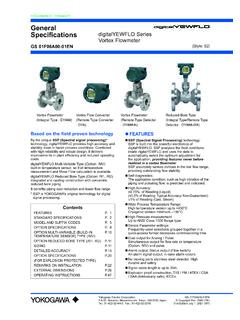
1 GS 01R01B02-00E-E Copyright October 2004 (RYG)28th edition, March 2019 (RYG) Model RAMCM etal Short-stroke ROTAMETERThe short-tube Rotameter is used for measurement of flow rates of liquids and gases. Its special application is in turbu-lent, opaque or aggressive fluids. The instrument is mounted in a vertical pipeline with flow direction upwards. Inside the special shaped conical Metal tube, a float is guided concen-trically. The position of this float is magnetically transmitted to the indicator. The indicators are exchangeable without influ-encing the Different process connections like flanges according to EN and ASME All wetted parts in stainless steel or PTFE Flow range water: to 130 m /h Flow range air: to 1400 m /h (+20 C, bar abs) Measuring accuracy acc.
2 Standard VDI/VDE 3513 sheet 2 (qG = 50 %) at calibration conditions Float damping to avoid float bouncing with gas applica- tions Optional heat tracing (with steam or fluid heat carrier) Indicator in steel or aluminum, protection class IP66/67 Mechanical indicator without additional power supply Microprocessor controlled transmitter with 24 V, 115 V or 230 V power supply Intrinsically safe version (Ex i): ATEX, IECEx, FM (C/US), NEPSI, PESO, EAC Flame proof version (Ex d): ATEX, IECEx, NEPSI, PESO, KOSHA, EAC, TS Dust explosion proof: ATEX, IECEx, NEPSI, TS Ex for non-electrical RAMC: ATEX, EAC FMEDA report available for SIL application Limit switches, also available as fail-safe version Electronic transmitter as standard with digital display with the following features.
3 Flow indication (totalizer, actual, percent) Indication of different volume- and mass flow units Possibility of user calibration in the field Float blocking indication function Adjustable signal output damping Error message indication Temperature measurement in the electronic transmitter HART 5/7-Communication ContentsFeaturespage 1 Standard Specificationspage 2 Hazardous Area Specificationspage 5 Planning and Installation Hintspage 10 Model Specificationspage 11 Optionspage 12 Process Connection Table for Metal Tubespage 15 Flow Table for Metal Tubespage 16 Process Connection and Flow Table for Metal Tubes with PTFE-liningpage 17 Temperature Limitations.
4 Standard and Intrinsically Safe page 18 Minimum Ambient Temperaturepage 19 Pressure Temperature (PT)-Ratingpage 20 Dimensions and Weightspage 21 GeneralSpecificationsRota Yokogawa GmbH & Co. KGRheinstr. 8D-79664 WehrGermanyGS 01R01B02-00E-ERAMC with housing type 90 RAMC with housing type 91GS 01R01B02-00E-E 28th edition, March 24, 2019-002 All Rights Reserved. Copyright 2004, Rota Yokogawa STANDARD SPECIFICATIONSRoHS Directive 2011/65/EU: RoHS conform according to EN 50581 MEASURING TUBEM aterials of wetted parts: Stainless steel AISI 316L ( ) PTFE (if selected) Gasket for process connection R4 or T4: Aramide fibres with NBR binder Other materials on requestFluids to be measured: Clean liquids, gas and steamMeasuring range: See table 10 and 11 Measuring turndown ratio: 10:1 Process connections/ Stainless steel: Flanges: Acc.
5 To EN 1092-1 DN100 to DN150 PN16 DN15 to DN100 PN40 DN50 to DN80 PN63 DN15 to DN50 PN100 Acc. to ASME B (AISI 316/316L dual certified) " to 6" Class 150 raised face " to 6" Class 300 raised face " to 3" Class 600 raised face Flange facing roughness Form B1: RA to Form B2: RA to ASME: RA to Threaded connection: Male acc. to DIN 11851 NPT-female G-female Clamp acc. to DN25, 1" to DN100, 4"Process pressure: Depends on process connection, see table 9 and 11 higher pressure (up to 700 bar) on request Process temperature: Wetted parts made of stainless steel: -196 C to +370 C Wetted parts made of PTFE: -80 C to +130 C See fig.
6 1a to fig. 1cMeasuring accuracy at calibration conditions: Table 1 Material of wetted partsSizeMeasuring accuracy acc. standard VDI/VDE 3513 sheet 2 (qG=50 %)SSDN15 to %SSDN125 to %PTFEDN15 to %Calibration conditions: Water, 1 to 2 bar, +15 C to +25 CPressure Equipment Directive (PED): Tubes: Modul: H Fluid Group: 1 (dangerous fluids) Produced acc. to category: III Classification: Table 6 of PED directive (piping) Heating (options /T1 to /T6): Art. 4 section 3: (Volume < 1 L) Fluid Group: 2 (non-dangerous fluids) Classification: Table 2 of PED directive (vessels)Installation: Mounting direction: vertical Flow direction: upwards Mounting length: see table 9 and 11 Straight pipe inlet length: DN80/100 at least 5D, not necessary for smaller sizesWeight: See table 17 Canadian Registration Numbers (CRN) Available upon requestMECHANICAL INDICATOR, type -TPrinciple: The flow values is indicated by a pointer with the aid of a magnet enclosed in the float and a magnet in the indicator unit which follows the movements of the housing.
7 Materials: Housing type 90: stainless steel Housing type 91: aluminum, Polyurethane, yellow, RAL 1021 acc. to EN 13195 material: AC 44200 Both housing types with safety-glass window Degree of protection: IP66/67 NEMA 4, 4X, 6 (not for Ex d housing)Scales: Standard: removable aluminium plate with scale (double scale as option) Marking: direct readable units or percentage of and Storage condition: -40 C to +110 C ELECTRONIC TRANSMITTER, type -E, -H, -JStandard type -E: Power supply: 4-wire units with galvanic isolation: 230 V AC +10 %/ -15 %, 50/60 Hz, fuse A, time lag, (5x20) mm 115 V AC +10 %/ -15 %, 50/60 Hz, fuse A, time lag, (5x20) mm 2/3-wire units: U = 14 to 30 V DC Output signal: 4-wire units: 0 to 20 mA 4 to 20 mA Pulse output (option /CP): max.
8 Frequency 4 Hz 3-wire units: 0 to 20 mA 4 to 20 mA 2-wire units: 4 to 20 mA The 20 mA point is selectable between 60 % and 100 % of scale end value. Load resistance: 4-wire units: 500 2/3-wire unit: (U - 14 V)/ 20 mA, max. 500 HART -communication type (Code -H, -J): Power supply: 2-wire units: U = 14 to 30 V DC Output signal: 2-wire units: 4 to 20 mA Load resistance: HART -version: 250 to 500 GS 01R01B02-00E-E 28th edition, March 24, 2019-003 All Rights Reserved. Copyright 2004, Rota Yokogawa LIMIT SWITCHES IN STANDARD VERSION, option /K1 to /K3 Type: Inductive proximity switch acc.
9 To EN 60947-5-6 Nominal voltage: 8 V DCOutput signal: 1 mA or 3 mA LIMIT SWITCHES IN FAIL-SAFE VERSION, option /K6 to /K10 Type: Inductive proximity switch ; acc. to EN 60947-5-6 Nominal voltage: 8 V DCOutput signal: 1 mA or 3 mA HYSTERESIS OF LIMIT SWITCHESMin-contact/ Max-contact: Pointer movement: mm Float movement: mmMinimum distance between 2 contacts: 2 mmCABLE GLAND, option /K1 to /K10 Size: Standard: for housing type 90 Standard: for housing type 91 Option /A13: thread Option /A5: thread NPT " Cable diameter: 6 to 9 mmMaximum cross section of core: mm POWER SUPPLY FOR LIMIT SWITCHES, option /W Type: Acc.
10 To EN 60947-5-6 KFA5-SR2-Ex*-W (115 V AC); * = 1 or 2 KFA6-SR2-Ex*-W (230 V AC); * = 1 or 2 KFD2-SR2-Ex*-W (24 V DC); * = 1 or 2 Fail-safe KHA6-SH-Ex1 (115/230 V AC), 1 channel KFD2-SH-Ex1 (24 V DC), 1 channel Power supply: 230 V AC 10 %, 45 to 65 Hz 115 V AC 10 %, 45 to 65 Hz 24 V DC 25 %Relay output: 1 or 2 potential-free changeover contact(s) Switching capacity: Max. 250 V AC, max. 2 ANote: If fail-safe limit switch option /K6 or /K7 is ordered, for the power supply option /W2E or /W4E must be selected. If fail-safe limit switch option /K8, /K9 or /K10 is ordered, for the power supply option /W2F or /W4F must be ) referenced to 20 C ambient temperatureDigital display: 8 digits, 7 segment LC-display character height 6 mmProcess-/ Ambient temperature: The dependency of the process temperature from the ambient temperature is shown in fig.