Transcription of Geometric Dimensioning and Tolerancing for …
1 Geometric Dimensioning and Tolerancing for Mechanical Design Answer guide 2 Geometric Dimensioning and Tolerancing for Mechanical Design Answer guide (Answers to the questions and problems at the end of each chapter) Geometric Dimensioning and Tolerancing for Mechanical Design Answer guide 3 Chapter 1 Introduction to Geometric Dimensioning and Tolerancing Chapter Review Page 7 1. Geometric Dimensioning and Tolerancing is a symbolic language used to specify the size , shape , form , orientation, and location of features on a part. 2. Features toleranced with GD&T reflect the actual relationship between mating parts. 3. Geometric Dimensioning and Tolerancing was designed to insure the proper assembly of mating parts , to improve quality , and reduce cost . 4. Geometric Tolerancing allows the maximum available tolerance and, consequently, the most economical parts.
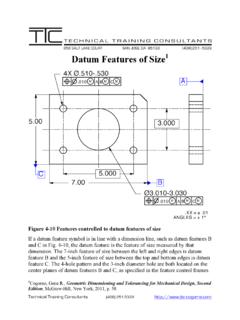
2 5. ASME 2009 is the current, authoritative reference document that specifies the proper application of GD&T. 6. Plus or minus Tolerancing generates a rectangular -shaped tolerance zone. 7. GD&T generates a cylindrical-shaped tolerance zone to control an axis. 8. If the distance across a square tolerance zone is .005 or a total of .010, what is the approximate distance across the diagonal? .007 or .014 9. Bonus tolerance equals the difference between the actual mating envelope size and the maximum material condition . 10. While processing, a rectangular part usually rests against a datum reference frame consisting of three mutually perpendicular planes. Geometric Dimensioning and Tolerancing for Mechanical Design Answer guide 4 Chapter 2 Dimensioning and Tolerancing Fundamentals Chapter Review Page 15 1. Each dimension shall have a tolerance except those dimensions specifically identified as reference, maximum, minimum, or stock.
3 2. Dimensioning and Tolerancing must be complete so there is a full understanding of the characteristics of each feature. 3. Dimensions shall not be subject to more than one interpretation . 4. The drawing should define the part without specifying manufacturing methods. 5. A 90 angle applies where center lines and lines depicting features are shown on a 2D orthographic drawing at right angles and no angle is specified. 6. A basic 90 angle applies where centerlines of features in a pattern or surfaces shown at right angles on a 2D orthographic drawing are located or defined by basic dimensions and no angle is specified. 7. All dimensions and tolerances are applicable at 68 F (20 C) unless otherwise specified. Measurements made at other temperatures may be adjusted mathematically. 8. All dimensions and tolerances apply in the free state condition except for non-rigid parts.
4 9. All tolerances apply for the full depth , full length , and full width of the feature unless otherwise specified. 10. Dimensions and tolerances apply only at the drawing level where they are specified. 11. Units of linear measurement are typically expressed either in the inch system or the metric system. 12. For decimal inch tolerances, a zero is never placed before the decimal point for values less than one inch. Geometric Dimensioning and Tolerancing for Mechanical Design Answer guide 5 13. For decimal inch tolerances, a dimension is specified with the same number of decimal places as its tolerance . 14. What are the two types of direct Tolerancing methods? Limit Dimensioning and plus and minus Dimensioning 15. For decimal inch tolerances, where a unilateral tolerance is specified and either the plus or minus limit is zero, its zero value will have the same number of decimal places as the other limit and the appropriate plus and minus sign.
5 16. For decimal inch tolerances, where bilateral Tolerancing or limit Dimensioning and Tolerancing is used, both values have the same number of decimal places 17. Dimensional limits are used as if an infinite number of zeros followed the last digit after the decimal point. 18. Angular units of measurement are specified either in degrees and decimal parts of a degree or degrees, minutes, and seconds . 19. What two dimensions are not placed on the field of the drawing? The 90 angle and a zero 20. If CAD/CAM database models are used and they do not include tolerances, tolerance values may be expressed in a CAD product definition data set. Geometric Dimensioning and Tolerancing for Mechanical Design Answer guide 6 Chapter 3 Symbols, Terms, and Rules Chapter Review Page 40 1. What type of Geometric tolerance has no datum features? Form controls 2. Which of the form tolerances is the most common?
6 Flatness 3. What type of Geometric tolerances indicates an angular relationship with specified datum features? Orientation controls 4. What is the name of the symbol that is used to identify physical features of a part as datum features and should not be applied to centerlines, center planes, or axes? Datum feature symbol 5. Datum feature identifying letters may be any letter of the alphabet except? I, O, & Q 6. If the datum feature symbol is placed in line with a dimension line or on a feature control frame associated with a feature of size, then the datum feature is what is what kind of feature? A feature of size 7. One of the 14 Geometric characteristic symbols always appears in the first compartment of the feature control frame. 8. The second compartment of the feature control frame is the tolerance section. 9. The tolerance is preceded by a diameter symbol only if the tolerance zone is cylindrical.
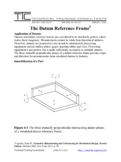
7 10. Datum features are arranged in order of precedence or importance . 11. Read the feature control frame in Figure 3-35 and write it below. The position tolerance requires that The axis of the controlled feature Must lie within a cylindrical tolerance zone .010 in diameter At maximum material condition (MMC) Geometric Dimensioning and Tolerancing for Mechanical Design Answer guide 7 Oriented and located with basic dimensions to a datum reference frame established by datum feature A and datum features B and C at their maximum material boundaries (MMB) 12. The all around and between symbols are used with what control? Profile 13. The all over symbol consists of two small concentric circles placed at the joint of the leader connecting the feature control frame to the feature. 14. The continuous feature symbol specifies that a group of two or more interrupted features of size are to be considered one single feature of size.
8 15. If no depth or remaining thickness is specified, the spotface is the minimum depth necessary to clean up the surface of the specified diameter. 16. The independency symbol indicates that perfect form of a feature of size at MMC or LMC is not required. 17. The unequally disposed profile symbol indicates that the profile tolerance is unilateral or unequally disposed about the true profile. 18. The datum translation symbol indicates that a datum feature simulator is not fixed and is free to translate within the specified Geometric tolerance. 19. The actual mating envelope is a similar, perfect, feature(s) counterpart of smallest size that can be contracted about an external feature(s) or largest size that can be expanded within an internal feature(s) so that it coincides with the surface(s) at the highest points. 20. A theoretically exact dimension is called?
9 A basic dimension 21. What is the theoretically exact point, axis, line, plane, or combination thereof derived from the theoretical datum feature simulator called? a datum 22. A datum feature is a feature that is identified with either a datum feature symbol or a datum target symbol. 23. A datum feature simulator (Physical) is the physical boundary used to establish a simulated datum from a specified datum feature. 24. A datum reference frame consists of three mutually perpendicular intersecting datum planes. 25. What is the name of a physical portion of a part, such as a surface, pin, hole, tab, or slot? A feature 26. A regular feature of size is a feature that is associated with a directly toleranced dimension and takes one of the following forms: a. A cylindrical surface b. A set of two opposed parallel surfaces c. A spherical surface Geometric Dimensioning and Tolerancing for Mechanical Design Answer guide 8 d.
10 A circular element e. A set of two opposed parallel elements Geometric Dimensioning and Tolerancing for Mechanical Design Answer guide 9 27. What is a feature of size with the maximum amount of material within the stated limits of size called? maximum material condition (MMC) 28. What is a feature of size with the least amount of material within the stated limits of size called? least material condition (LMC) 29. What kind of feature always applies at MMC/MMB, LMC/LMB, or RFS/RMB? a feature of size or a datum feature of size 30. The maximum material condition modifier specifies that the tolerance applies at the maximum material condition (MMC) size of the feature. IndividualFeatureOnlyIndividualFeatureor RelatedFeaturesSYMMETRYCONCENTRICITYPOSI TIONS ymbolSTRAIGHTNESSFLATNESSCIRCULARITYCYLI NDRICITYPROFILE OF A LINEPROFILE OF A SURFACEG eometric CharacteristicsANGULARITYPERPENDICULARIT YPARALLELISMCIRCULAR RUNOUTTOTAL RUNOUTR unoutLocationOrientationRelatedFeaturesP rofileFormType of TolerancePertains to Figure 3-36 Geometric characteristic symbols.