Transcription of Geometric Dimensioning and Tolerancing - IVCC
1 Geometric Dimensioning and TolerancingCAD 2204 Spring 20101 Introductions Syllabus My expectations for the class Your expectationsCAD 22042 Instructor Introduce yourself and tell me one expectation you have for this The syllabus contains the written class expectations for learning and behavior. Not all situations are covered. If a question arises not covered then the student handbook and College rules will Hearing spoken text and looking at graphics ? 91% more learning, Looking at graphics alone ? 63% more, Reading printed text plus looking at graphics ? 56% more, Listening to spoken text, reading text, and looking at graphics ?
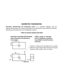
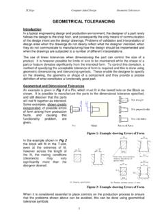
2 46% more, Hearing spoken text plus reading printed text ? 32% more, Reading printed text alone ? 12% more, Hearing spoken text alone ? 7% We learnChapter OneEngineering Drawings and Tolerancing6 Understand what an engineering drawing is Understand why Geometric Tolerancing is superior to coordinate tolerancing7 Chapter Goals A document that communicates a precise description of a part. The description will consist of pictures, words, numbers and is an Engineering Drawing? An engineering drawing may communicate the following: Geometry of the part Critical functional relationships Tolerances Material, heat treat, surface coatings Part documentation such as part number and drawing revision number9 What is an Engineering Drawing?
3 Note the dimensions10 What is an Engineering Drawing?11 What is an Engineering Drawing? Electrical Quality/Descriptive Papyrus/Rock/Clay tablet Sumerian, Egyptian and other early civilizations. Pen and Ink Pencil Mainframe PC Several different software's AutoCAD Pro-E12 Brief History of Engineering was wrong with the way we always made our drawings?13 Drawing errors compound the cost of the error as you move further from initial design to production. Drawing errors cost: Money Time Material Customer satisfaction14 Cost of Drawing Errors!What Else Was Wrong?15 Disagreements over drawing communicating drawing not understand the designer s intent.
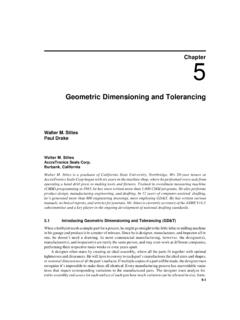
4 Bad parts passing inspections. Wasting money on parts that do not Else Was Wrong? Dimensions A numerical value expressed in appropriate units of measure and used to define the size, location, orientation, form or other Geometric characteristics of a part17 Back To Engineering Drawings! Tolerance Tolerance is the total amount a specific dimension is permitted to vary from the specified dimension. The tolerance is the difference between the maximum and minimum Drawings Limit Tolerance: When a dimension has a high and low limit stated. is a limit tolerance. Plus-Minus Tolerance The nominal or target value of the dimension is given first, followed by a plus-minus expression of tolerance.
5 32 + is a plus-minus of Tolerances Bilateral Tolerance A tolerance that allows the dimension to vary in both the plus and minus directions. Equal Bilateral Tolerance Variation from the nominal is the same in both of Tolerances Unilateral Tolerance Where allowable variation is only in one direction and zero in the other. Unequal Bilateral Tolerance Where the allowable variation is from the target value and the variation is not the same in both directions. Figure 1-4, page 7 for of Tolerances For this class we will be using metric dimensions. Drawings must state the units used and certain other information used in the drawing.
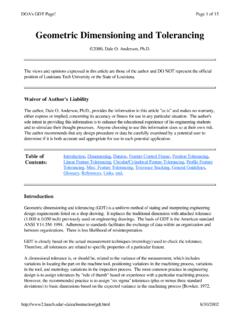
6 22 Metric Dimensions The primary ways to indicate tolerances in a drawing are: A general tolerance note A note providing a tolerance for a specific dimension A reference on the drawing to another document that specifies the required tolerances These are similar to specifying dimension units23 Metric Dimensions When a metric dimension is a whole number, the decimal point and zero are omitted. Ex. 56 When a metric dimension is less than one millimeter, a zero precedes the decimal point. Ex. When a metric dimension is not a whole number, a decimal point with the portion of a millimeter (10ths or 100ths) is specified.
7 Ex. Dimension Rules All Dimensioning limits are absolute That is all dimensions are considered to have a zero after the last true digit. Ex. means See page 8 for other examples This interpretation is important for gauging. A part with a dimension and tolerance of + would fail inspection at what Measure? 25 Dimensioning Limits History of GD&T Drawings before industrial evolution were elaborate pictures of a part that could not be made today. Why? Parts made were unique one of a kind that were made as the craftsman saw the part. The industrial revolution made manufacturers realize that one of a kind was not History Mass production created the need for interchangeable parts.
8 This meant drawings that were simple and standardized. The first standard was coordinate based. 1966 saw the publication of the first GD&T standard ANSI Updates have been published in 1982, 1994 and History Ten rules apply to our work. They are based on ANSI Each dimension shall have a tolerance except those dimensions specifically identified as reference, maximum, minimum or stock size. These terms are explained later in the text. Dimensioning and Tolerancing shall be complete so there is full definition of each part Dimensioning Rules Dimensions shall be selected and arranged to suit the function and mating relationship of a part and not be subject to more than one interpretation.
9 These three rules establish Dimensioning Dimensioning Rules The drawing should define a part without specifying manufacturing methods. A 90 degree angle applies where centerlines and lines depicting features are shown on a drawing at right angles and no dimension is shown. 30 Fundamental Dimensioning Rules A 90 degree basic angle applies where centerlines of features in a pattern or surfaces shown at right angles on a drawing, are located and defined by basic dimensions and no angle is specified. These last two rules establish convention for implied 90 degree angles. 31 Fundamental Dimensioning Rules Unless otherwise specified, all dimensions are applicable at 20 degrees Centigrade (68 deg.)
10 F) What happens in other types of weather? All dimensions and tolerances apply in the free-state condition. This condition does not apply to non-rigid parts. Unless otherwise specified, all Geometric tolerances apply to the full depth, length and width of the feature. These three rules establish default conditions for dimensions and tolerance Dimensioning Rules Dimensions and tolerances apply only at the drawing level where they are specified. A dimension specified on a detail drawing is not mandatory for that feature on the assembly drawing. 33 Fundamental Dimensioning Rules Coordinate Tolerancing is a Dimensioning system where a part feature is located by a means of rectangular dimensions with given tolerances.