Transcription of GETTING STARTED WITH PROGRAMMABLE LOGIC DEVICES, …
1 1 GETTING STARTED with PROGRAMMABLE LOGIC devices , THE 16V8 AND 20V8 Robert G. Brown All Rights Reserved August 25, 2000 Alta Engineering 58 Cedar Lane New Hartford, CT 06057-2905 (860) 489-8003 2 Hands on Design with PROGRAMMABLE LOGIC devices The introduction of PROGRAMMABLE LOGIC devices (PLDs) was a great boon to the field of digital hardware design. The second generation PLD, the GAL (which stands for Generic Array LOGIC , a trademark of Lattice Semiconductor) is particularly suited for the small scale hardware designer. GALs offer the following benefits to the hardware designer: Flexibility - GALs are very flexible devices , they can implement both combinatorial LOGIC functions (AND, OR, NAND etc.)
2 And registered LOGIC functions (counters, shift registers etc.) on the same chip. PAL replacement- The GAL16V8 and GAL20V8 each can directly replace over 20 of the common PAL ( PROGRAMMABLE Array LOGIC - the first generation PLD) types each. This means you only need to stock 2 GAL types to handle your PLD needs. Space savings - In my experience each GAL has typically replaced between 2 and 4 standard TTL chips, saving a large amount of board space. Speed - GALs are fast devices with propagation delay down as low as 7 ns. Typical GALs have a propagation delay of only 15 ns - faster then standard 7400 or 74LS series LOGIC . Reprogrammability - Not only are GALs PROGRAMMABLE giving the ability to correct design errors and make board layout easier, they can be reprogrammed up to 100 times.
3 Erasing and programming takes only a few seconds. Cost - In addition to the savings in PC board real estate, standard speed GAL16V8s and GAL20V8s (25 and 15 ns) cost only a few dollars even in small quantities. There are several varieties of GALs but I will limit this article to the GAL16V8 and GAL20V8. They are easy to design with and are the least expensive and most readily available GAL devices . Rather then get bogged down with the internal details of the devices , we'll cover what is needed to use these PLDs in your designs and then look at a real life design example. The Device Architecture The GAL16V8 is commonly packaged in a standard 20 pin DIP and the GAL20V8 is commonly packaged in a 24 pin skinny DIP (a 24 pin skinny DIP is inches wide, the same width as a 20 pin DIP and half the width of a standard 24 pin DIP).
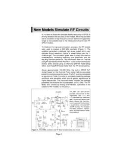
4 The pinout for both devices is shown in figure 1. For the GAL16V8 pin 10 is the ground pin and pin 20 the +5 volt pin (VCC). Pins 12 through 19 are each connected to Output LOGIC Macro Cells (OLMC). The OLMC allows these pins to act as inputs, combinatorial outputs, registered outputs and input/output pins. Pins 2 through 9 are always general purpose input pins. If any of the OLMC are configured as registered outputs then pin 1 is a Clock input and pin 11 is the Output Enable for the registered outputs. If none of the OLMC 3 are registered then pins 1 and 11 are general purpose inputs. Internal to the chip is an array of and/or LOGIC that is configured with each OLMC when the chip is programmed.
5 The 20V8 has a similar design, the main difference from the 16V8 is the four additional input pins. The Design Tools In addition to your PC you will need only three tools to do design work with PLDs, a text editor, a LOGIC compiler and a device programmer. A LOGIC compiler is a program that translates a high level design file, in which the relationship between inputs and outputs is expressed in the form of equations, to a low level file device specific file for the programmer. The low level file used by the programmer is called a JEDEC file and is sometimes referred to as a 'fuse map'. (Earlier PLDs were programmed by literally blowing up fuses internal to the device leaving only the desired connections - of course they could not be reprogrammed - you threw away your mistakes.)
6 National Semiconductor used to offer a FREE LOGIC compiler before they got out of the PLD business. You can still get a copy of their PLAN LOGIC compiler off of the Alta Engineering web site at The high level design file for PLAN is called an equation file and uses the extension .EQN, the output JEDEC file uses the extension .JED. Since PLAN is available to everyone I will use it in the examples, the concepts however are universal, not specific to PLAN. The equation file is a standard ASCII text file and can be produced using any text editor. Designing with Equations If you normally design with standard TTL devices , shifting to design using GALs might take a slight adjustment. However the underlying concepts are the same.
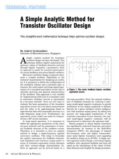
7 In the equations a + is used to represent OR, a * to represent AND a / for NOT or inversion. In figure 2a show the equation represent by an AND gate. Each group of signals ANDed together is referred to as a product term. Figure 2b shows the equivalent representation for a two input OR gate. In figure 2c a more complicated piece of LOGIC is represented, it includes the use of the / symbol to show inversion. Notice how the equation is organized. The equations are written in a sum of products format, a useful convention is to list each product term on a separate line. The inversion can also occur on the output as shown is in figure 2d. In the 16V8 and 20V8 up to eight outputs can be defined in this way (each of the eight OLMC).
8 The inputs for the equations can come from any of the input or output pins either normal or inverted. A maximum of seven or eight product terms are allowed for each OLMC, this depends on the exact configuration of the OLMC. Given this, it is obvious that a single GAL can replace several packages of AND, NAND, NOR and OR gates. But this is only the start. So far all the examples have used combinatorial LOGIC , in addition GALs can also handle sequential LOGIC such as shift registers and counters. To do this the OLMC is configured as a register (D flip flop). If any of OLMC are configured as registered then pin 1 is the clock input to the register. Where as an = symbol is used to show a combinatorial output in an equation, a := symbol is used to show a registered equation output.
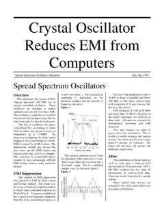
9 For example: 4 Q := D The := indicates that the output Q is registered. This means that Q will take on the value of D following the rising edge of the clock on pin 1. Two or more outputs can be combined to form counters and shift registers as shown in figure 3. In this case it shows a two bit counter with a terminal count. The two outputs Q0 and Q1 will count from 0 to 3 continuously and the terminal count indication will be active when the count is at its maximum value of 3. The registered outputs have a common output enable at pin 11 on a 16V8 and pin 13 on a 20V8. When output enable is low the registered outputs are all enabled. If output enable goes high all the registered outputs will be disabled (tri-stated).
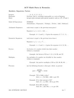
10 Even when the outputs are tri-stated the register outputs are still available internally as feedbacks (so the counter would continue to work even if the outputs were disabled). Combinatorial outputs can each have an output enable defined, this is limited to a single product term. For example: = B * C This would indicate that output X should be enabled when B AND C are high. A Real Design Example To illustrate the use of GALs in a real design, I will use the main board from a high speed, low cost 16 channel LOGIC analyzer. The LOGIC analyzer main board uses a total of 17 ICs, of these 2 are static RAMs, 4 are octal latches, 4 are octal buffers and the remaining 7 are programmed GAL16V8s. All standard LOGIC was handled by the 7 Gals, they replace about 20 high speed TTL ICs and make the LOGIC analyzer buildable.