Transcription of GettingStartedwithRevit Architecture
1 RevitArchitectureGettingStartedwithRevit Architecture 2008 Autodesk, Inc. All Rights Reserved. Except as otherwise permitted by Autodesk, Inc., this publication, or parts thereof, may not bereproduced in any form, by any method, for any purpose. Certain materials included in this publication are reprinted with the permission of the copyright holder. DisclaimerTHIS PUBLICATION AND THE INFORMATION CONTAINED HEREIN IS MADE AVAILABLE BY AUTODESK, INC. "AS IS." AUTODESK, INC. DISCLAIMSALL WARRANTIES, EITHER EXPRESS OR IMPLIED, INCLUDING BUT NOT LIMITED TO ANY IMPLIED WARRANTIES OF MERCHANTABILITY ORFITNESS FOR A PARTICULAR PURPOSE REGARDING THESE MATERIALS. TrademarksThe following are registered trademarks or trademarks of Autodesk, Inc., in the USA and/or other countries: AutoCAD, Autodesk, Autodesk(logo), ViewCube, SteeringWheels and other brand names, product names or trademarks belong to their respective Party Software Program CreditsACIS Copyright 1989-2001 Spatial Corp.
2 Portions Copyright 2002 Autodesk, 1997 Microsoft Corporation. All rights CorrectSpell Spelling Correction System 1995 by Lernout & Hauspie Speech Products, All rights Copyright 1997 InstallShield Software Corporation. All rights and other Pantone, Inc. trademarks are the property of Pantone, Inc. Pantone, Inc., Copyright 1991-1996 Arthur D. Applegate. All rights relating to JPEG Copyright 1991-1998 Thomas G. Lane. All rights reserved. Portions of this software are based on the work of theIndependent JPEG from the Bitstream typeface library copyright from Payne Loving Trust 1996. All rights Objects Engine 2005 SAFE Software. All rights is a registered trademark of Computers and Structures, Inc. ETABS copyright 1984-2005 Computers and Structures, Inc. All is a trademark of RISA Technologies.
3 RISA-3D copyright 1993-2005 RISA Technologies. All rights relating to TIFF Copyright 1997-1998 Sam Leffler. Copyright 1991-1997 Silicon Graphics, Inc. All rights of Libxml2 Copyright 1998-2003 Daniel Veillard. All Rights UseUse, duplication, or disclosure by the Government is subject to restrictions as set forth in FAR (Commercial ComputerSoftware-Restricted Rights) and DFAR (Rights in Technical Data and Computer Software), as 1 Getting Started .. 1 Introduction .. 1 Creating a Project .. 3 Creating Walls .. 6 Creating Terrain .. 7 Adding Exterior Walls .. 10 Adding a Roof .. 11 Adding Floors .. 13 Adding Interior Walls .. 15 Adding Doors .. 17 Adding Windows .. 19 Adding a Curtain Wall .. 23 Attaching Walls to the Roof .. 24 Modifying the Entry Deck .. 25 Adding a Sloped Floor.
4 28 Adding Stairs and Railings .. 29 Modifying the Roof .. 34 Documenting the Project .. 35 Creating a Solar Study .. 40 Creating a Sheet .. 41iiiivGetting StartedWelcome to revit Architecture 2009! We hope you enjoy learning and using this revolutionary parametric buildingmodeller. revit Architecture is designed to accommodate various ways of working, so that you can concentrate on yourbuilding models rather than on adapting your methodology to the demands of the software. In this short tutorial, youlearn how to use the features of revit Architecture to design, change, and document a building. You learn how you canmake design changes in any view of the building, and the parametric change engine in revit Architecture coordinatesthose changes in all other beginning the exercises, install the software and register it as either demo or subscription.
5 Demomode serves as a no-cost viewer, allowing you to export, print, or plot projects that have not been and Metric ConventionThe exercises in this guide contain both imperial and metric values. This means that when you see animperial value, a metric value is displayed in square brackets next to example: In the Type Selector, select Basic Wall : Generic - 6'' [200mm].All audiences using the metric measurements should follow the metric values in brackets only; all metricmeasurements are in millimeters. Note that the imperial and metric values are not direct conversions, butappropriate values for completing either the imperial or metric the User InterfaceWhen the revit Architecture window is displayed, take a minute to view the different Bar and ToolbarsAt the top of the window is the standard Microsoft Windows -based menu bar, from which you can accessall revit Architecture commands.
6 Icons on the toolbars are buttons for executing common revit BarBelow the toolbars is the Options Bar, which displays command options for the current operation. If youclick Wall on the Design Bar on the left side of the revit Architecture window, the Options Bar displaysoptions related to the Wall SelectorOn the left side of the Options Bar is the Type Selector, a drop-down menu that lists different types ofelements to add to a project. You can choose an element type by selecting it from the drop-down menu ofthe Type ButtonTo the right of the Type Selector is the Properties button , which accesses a dialog in which you canchange various parameters of a selected BarOn the left side of the revit Architecture window is the Design Bar, which lists the commands available forthe currently selected tab. There are 10 tabs: Basics, View, Modelling, Drafting, Rendering, Site, Massing,Room and Area, Structural, and Construction.
7 To see all the tabs, right-click on the Design Bar. To displaya single tab, click the tab | Chapter 1 Getting StartedProject BrowserTo the right of the Design Bar is the Project Browser. The Project Browser is a listing of all views, families,and groups in the project. You can select any of the items listed in the Project Browser. A convenient wayto open a view is to double-click the view name in the Project Browser BarAt the lower left corner of the drawing area is the Status Bar, which displays the status of the current commandor the name of a highlighted Control BarAt the lower left corner of the drawing area, above the Status Bar, is the View Control Bar. The controls aregraphical shortcuts to various View commands, namely scale, detail level, graphics style, advanced modelgraphics, shadows, crop region, and temporary hide/isolate.
8 Some views, such as sheets, drafting, and renderedviews, have limited AreaThe drawing area of the revit Architecture window displays views (and sheets and schedules) of the currentproject. By default, each time you open a view in a project, the view displays in the drawing area on top ofother open views. You can use commands on the Window menu to arrange the project CenterThe Communication Center provides quick access to resources at Autodesk, such as Live Update maintenancepatches, subscription information, articles, tips, and product support information. For more information,see the revit Architecture StartedNow that you have explored the interface, you can start your first project. In this project, you use some ofthe basic commands found in revit Architecture . The exercises show how easy it is to design a simple buildingwith no previous a ProjectIn this first exercise, you create and name a project in which you will create the building model a Project | 31 Create a project: In the drawing area, under Projects, click New.
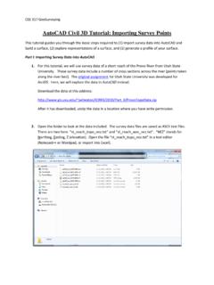
9 In the New Project dialog, under Create New, verify that Project is selected. Under Template file, verify the second option is selected, and click Browse. In the left pane of the Choose Template dialog, click Training Files, and open\Imperial\Templates [Metric\Templates]. Select [ ], and click Open. In the New Project dialog, click and save the project file: Click File menu Save. In the left pane of the Save As dialog, click Training Files, and then, in the file window,double-click Imperial [Metric]. For File name, enter Getting_Started, and click to a view: In the Project Browser, double-click Elevations (Building Elevation) South. Enter ZR, to zoom to a specific that the cursor changes to a magnifying glass. In the drawing area, move the cursor diagonally and click to draw a rectangle around thelevel area within the rectangle is magnified to fill the drawing area so that you can work withthe level marker | Chapter 1 Getting Started4 Rename levels: Double-click the Level 1 text, enter 00 Foundation, and press a number as a prefix to the name so the plans are sorted by level.
10 In the alert dialog, click Yes to rename corresponding floor and ceiling plans for Level 1 are renamed 00 Foundation. Using the same method, rename Level 2 and its corresponding views as 01 Lower levels in the building: Enter ZO to zoom out. On the Design Bar, click Level. On the Options Bar, click (Pick Lines), and, for Offset, enter 10' [3000mm]. In the drawing area, highlight the 01 Lower Level line; when a dashed line is displayed abovethe level line, click to create a level (Level 3). Using the same method, create a level above Level the Design Bar, click Modify to end the the new levels and all corresponding views: Level 3: Rename as 02 Entry Level Level 4: Rename as 03 Roof8 Double-click the level dimensions, and enter new values: 0'0'' [0mm]: Change to -14'0'' [-5250mm] 10'0'' [4000mm]: Change to -10'0'' [-3050mm]Creating a Project | 5 20'0'' [7000 mm]: Change to 0'0'' [0 mm] 30'0'' [10000 mm]: Change to 10'0'' [3050 mm]9On the Design Bar, click the project WallsIn this exercise, you work on different levels to add foundation walls to the the Project Browser, under Floor Plans, double-click 00 Foundation to open that view in thedrawing the Design Bar, click the Type Selector, select Basic Wall : Retaining - 12'' Concrete [Basic Wall : Retaining - 300mmConcrete].