Transcription of GMU - ECE 739, Fall 2003 - Satellite Communications Class ...
1 GMU - ECE 739, Fall 2003 - Satellite CommunicationsClass: Nov-17-2003(C) Leila Z. Ribeiro, 20031 ECE 739 Fall 2003 Satellite CommunicationsLecture 11 earth station Technology, VSATs and Network ArchitecturesDr. Leila Z. RibeiroNovember 17, 20032 Agenda earth station design earth station types VSATs Satellite networksEarth station Design4 earth station Technology Recall from previous classes:srttTGRkBGPNC24 = This is the ratio that interests us hereThe ratio between the gain of the antenna, Gr, and the system noise temperature, Ts, is often referred to as the quality factor of the earth station antennaGMU - ECE 739, Fall 2003 - Satellite CommunicationsClass: Nov-17-2003(C) Leila Z. Ribeiro, 200325 earth station StandardsService earth station TypeApproximate G/T (dB/K)CommentsFSSL arge40 Medium30 Small25 Very Small20 Transmit/ReceiveVery Small12 Receive onlyMSSM obile earth StationLarge-4 Tracking RequiredMedium-12 Tracking RequiredSmall-24 Without TrackingBSSUser earth StationLarge15 Used for community receptionSmall8 Used for individual reception6 earth station Design Considerations Type of service (FSS, MSS, etc.)
2 Type of communication (data, voice, TV, etc.) Baseband S/N ratio requirements Traffic requirements (number of users, etc.) Traffic type (continuous or bursty) CostG/T, Tx. power, MA scheme, Antenna Feed Tracking Low-noise amplifier (LNA) High-power amplifier (HPA) earth station RF Subsystems8 Antennas are of two basic types with regards to axis: Axially-Fedand Offset-FedOffset-fed reduce blockage and increase polarization isolation. There are three basic antenna designs: Front-fed, Cassegrainand GregorianThe longer focal length of the Cassegrain and Gregorian antennas (both back-fed ) give better off-axis performance and sidelobe controlAntenna Review (1)GMU - ECE 739, Fall 2003 - Satellite CommunicationsClass: Nov-17-2003(C) Leila Z.
3 Ribeiro, 200339 Axially FedAntenna Review (2) Front-Fed antennas:Offset FedParaboloidal main reflectorMain reflector is a portion of a paraboloid10 Hyperboloidalsub-reflectorMain reflector is a paraboloid with an on-axis hole for the feedAntenna Review (3) Cassegrain (most popular for large earth stations)Axially FedOffset FedMain reflector is a portion of aparaboloidHyperboloidalsub-reflector11 Elliptical sub-reflectorAntenna Review (4) GregorianAxially FedOffset FedMain reflector is a paraboloid with an on-axis hole for the feedMain reflector is a portion of aparaboloidElliptical sub-reflector12 Gain, G, of an antenna influenced by 1) antenna dimensions, 2) illumination efficiency of antenna (by the feed system), 3) overall efficiency of the antenna itself For a circular aperture antenna, gain is given byOverall efficiency -usually 55 to 60 %Alternative rule of thumb: 3dBis in degreesAntenna Gain ReviewAntenna diameterGMU - ECE 739, Fall 2003 - Satellite CommunicationsClass: Nov-17-2003(C) Leila Z.
4 Ribeiro, 2003413Co-polarized antenna patternCross-polarized antenna patternNote:The cross-polarized antenna pattern has a deep null on axis. In this case, the on-axis XPI = 30 dB0 dB-15 dB-30 dBCo- and Cross-Polarized Beams14 To illuminate main reflector To separate transmit and receive bands To separate and combine polarizations To provide error signals for some types of tracking systemsFeed System Functions15 Antenna can be fixed to its mount (no tracking) as long as the stationkeeping error is well within the 3 dB beamwidth. Otherwise, tracking is needed (even for GEOs). Tracking is more important for dual-polarized antennas due to the steep null (generally on axis) for the opposite polarization sense Three main types of antenna tracking: Step tracking low cost, simplest Conical scan intermediate trade-off Monopulse best accuracy, most complex and expensiveAntenna Tracking16 Step Tracking Antenna beam is shifted in steps, by moving the feed horn position of the parabolic antenna.
5 Received signal in each step is compared with previous. Target position is found when two consecutive positions provide the same signal strength. Method is relatively - ECE 739, Fall 2003 - Satellite CommunicationsClass: Nov-17-2003(C) Leila Z. Ribeiro, 2003517 Conical Scanning Antenna beam is rotated around a circle, scanning a conical volume around the target. Implemented by rotating the feed horn around the axis of the parabolic antenna. When target is at center of conical scan, the signal strength from all samples around the cone are equivalent. When target is off-center, the amplitude of received signal varies as beam More accurate than step tracking and conical scan. Two or more beams transmitted simultaneously. Uses only one paraboloid reflector, but multiple feed horns.
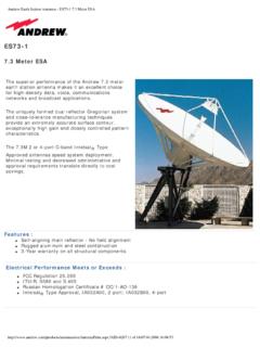
6 Most complex and expensive & HPAs LNAs GaAsFET HPAs Smaller earth stations use solid state power amplifiers(SSPAs) : Watts Large earth stations use traveling wave tube amplifiers(TWTAs): 10-15 kWatts or klystrons: 3 kW => Also cause many E/S failuresTypes of earth StationsGMU - ECE 739, Fall 2003 - Satellite CommunicationsClass: Nov-17-2003(C) Leila Z. Ribeiro, 2003621 E/S capable of transmitting and receiving Antenna sizes vary from m (VSAT) to about 30 m Two types of earth stations considered here: Large earth stations Very small aperture terminals (VSATs)Fixed Satellite Service (FSS)22 Typically reflector antennas Cassegrain types becoming popular Typical intelsat earth stations Large antennas => small beamwidths Tracking needs to be accurate to about 3dB/10 Fixed Satellite Service (FSS).
7 Large earth Stations23 Typically reflector antennas ( to m in the Ku band) Solid-state power amplifiers (1-2 W output power) Low-noise amplifier Usually uses low-noise converter, where down-conversion and amplification are performed in the same unit Usually power-limited, coding employed Convolutional coding & Viterbi decoding commonFixed Satellite Service (FSS):VSATs24 Limited mounting space implies that antenna size is severely restricted earth station cost should be kept low Traffic flow usually low Power consumption should be kept low Battery life restrictions Safety issuesMobile Satellite Service (MSS)GMU - ECE 739, Fall 2003 - Satellite CommunicationsClass: Nov-17-2003(C) Leila Z. Ribeiro, 2003725 Consist of a stabilized antenna system on a ship, an outdoor electronics unit and an indoor electronics unit connected to peripherals Outdoor section (above deck unit) Stabilized antenna, with auto-track facility Outdoor electronics for amplification and down-conversion to intermediate frequency Antenna dish ~90 cm (approx.)
8 21 dB, 15 degrees beamwidth at L band) Indoor section (below deck unit) Main electronics. Peripherals include telephone, telex and display/control units. EIRPs between 33 to 36 dBWMobile Satellite Service (MSS):Large earth Stations (Inmarsat B)26 Small ships and some vehicular systems Less complex EIRP around 12 dBW Smaller antennas Lower data ratesMobile Satellite Service (MSS):Small earth Stations (Inmarsat C)27 Universal Mobile Telephone System (UMTS) & Personal Communication Systems (PCS) Low cost, hand-held terminals Dual mode: Satellite and terrestrial supported earth station cost has to be kept low to allow market penetration for personal Communications Very low power due to battery and safety constraintsMobile Satellite Service (MSS):Small earth Stations (Handsets)28 VSATsGMU - ECE 739, Fall 2003 - Satellite CommunicationsClass: Nov-17-2003(C) Leila Z.
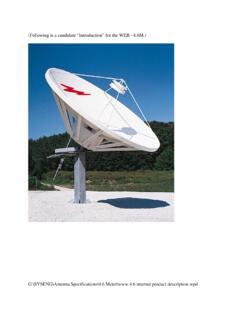
9 Ribeiro, 2003829 VSATs: Introduction VSAT = Very Small Aperture Terminal Early earth stations in commercial systems were very large and expensive (30 m) Need arose to make systems more affordable to users Increased transmit power from Satellite Go to higher frequencies Result: Smaller E/S antenna size allowable30 Large Antenna Systems Breakpoint between large and small antennas is at about 100 wavelengths Above breakpoint, back-fed configurations such as Cassegrain or Gregorian are economically and technically viable (sub-reflectors need to be at least 10 wavelengths) Below breakpoint, terminals called small aperture terminals (typically front-fed) Smaller antennas tighter link budgets31 VSAT Antenna Sizes At C-band: Below 5 meters (100 wavelength at 6 GHz) Standard VSAT antennas (provided by intelsat standards ) Smaller antennas are also included in the concept of VSAT: USAT = Ultra Small Aperture Terminal.
10 (DTH, MSS, etc).32 intelsat Standard for VSAT antennasSummary of Characteristics for the intelsat VSAT IBS Antennas From intelsat earth station standards (IESS) 207 (C-Band) and 208 (Ku-Band) (2) C-Band Antenna Standard F1 H4 H3 H2 G/T (4 GHz), dB/K Typical Antenna Diameter, m Voltage Axial Ratio (Circular Polarization): XPD Isolation Value, dB: dB dB dB dB Ku-Band Antenna Standard E1 K3 K2 G/T (11 GHz), dB/K Typical Antenna Diameter, m Voltage Axial Ratio (Linear Polarization): XPD Isolation Value, dB: dB dB dB Picture copyrighted. Reproduction with permission - ECE 739, Fall 2003 - Satellite CommunicationsClass: Nov-17-2003(C) Leila Z.