Transcription of GREENHECK
1 Installation, Operation and Maintenance InstructionsforMODEL KSU make -UP AIR UNITSPart # 457615 March 2000 GREENHECK BOX 410 SCHOFIELD, WISCONSIN 54476-0410PH. 715-359-6171 WARNING: Improper installation, adjustment, alteration, service or maintenance can cause property damage,injury or death. Read the installation, operating, and maintenance instructions thoroughly beforeinstalling or servicing this manual is the property of the owner, and is required for future leave it with the owner when you complete the IOM is for installation, operation, and maintenance of a KSU unit . For information on installation and maintenance of heating or cooling options reference the following manuals: Direct Gas (Part # 456857) Evaporative Cooling (Part # 456858) Steam, Hot Water, DX and Chilled Water Coils, and Electric Heat (Part # 457046) Pack Blast.
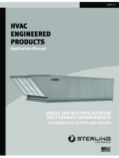
2 10 Dimensions and Weights ..11 of ContentsHousing Size#1#2#3A - Max Roof "35"47"B - Max. Roof "83"105"C - CLto CLof ducts36"48"58"D - Duct CL to Edge of Open. 121/2"171/2"231/2"Supply Duct CL toE -761/2"811/2"881/2" Equip. Support CL SupplyDuctworkby OthersExhaustDuctworkby OthersBCDAEDA/2 CurbFootprintEquipmentSupportFootprintRo ofOpeningC LC LC LExhaustDuctSupplyDuctMetal CoverEquipmentSupportRoof CurbExhaustSupply1" InsideFlangeInstallation with Fan Package ExtensionStep 1 Roof OpeningDetermine the center of the exhaust and supplyduct roof openings. The chart below shows themaximum recommended roof opening dimensions. These sizes can be smaller based on codes and ductwork 2 Install Roof Curb and EquipmentSupportCenter curb over roof openings and place on theroof.
3 Level the curb and shim if necessary. Attachcurb to roof and flash in install equipment support, refer to the chart instep 1 for dimensional location based on KSU unit size. Attach to roof in the same manner as the curb, remove metal cover, flash to wooden nailer and reinstall : Equipment support height = Curb Height + 4 .Step 3 Install Curb ExtensionInstall curb extension over curb, use wood screws tolag in place. Prepunched holes are provided. Locateextension so the tall, louvered side is over theexhaust opening, as shown in 4 Install DuctworkExhaust:Exhaust ductwork must be built in accordance with NFPA 96 and any local codes. Ductwork terminating at the fan should be square in shape or of smooth transition so as not to to affect the fans performance.
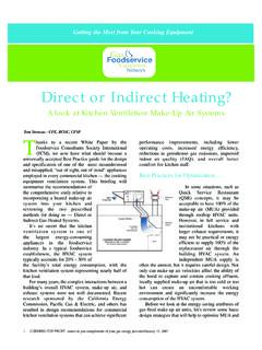
4 Supply:The chart at left shows the duct sizes and straight lengths recommended for optimal performance (AMCA Publication 201-90). Using duct sizes less than the recommended lengths will affect fan performance. Good duct practicesshould be followed for the remaining beginning this installation:When locating this unit , make sure that there is room toaccess the unit from all sides. The inlet must be located atleast 10 feet away from any exhaust vents. If this unit isdirect fired gas without insulation, the clearance toleranceto combustibles is 6 on all sides, top, and Supply Ductwork SizesStraight BlowerDuctDuctSizeSizeLength10813 x 1337 10913 x 1337"11014 x 1447"11216 x 1654"11520 x 2068"11824 x 2481"12026 x 2696"Supply Duct with DuctAdapter InstalledExhaust Duct InstalledSealantModel CUBEE xhaust FanModel KSUS upply UnitLifting Lugs(4 places)Step 4 use of a duct adapter with the supplyduct is strongly recommended to properlyalign the ductwork with the supply fandischarge.
5 The duct adapter is only a guideand is not intended to be used as support forthe ductwork. Step 5 Apply SealantBefore installing fans, apply a sealant aroundthe perimeter of the exhaust and supply ductadapter to isolate the fan and minimizevibration. Step 6 Install Exhaust FanInstall CUBE exhaust fan on curb with self-tapping sheet metal screwsthrough existing holes in curb cap. NFPA 96requires the exhaust fan be offers an optional hinge kit withrestraining cables and a grease trap withdrain connection. Install these options atthis time. NOTE: Installing the exhaust fan prior to thesupply unit will allow for easier installationof 7 Install Supply UnitUse a crane and a spreader bar hooked tothe factory lifting lugs (as shown in thediagram) to lift and center the KSU unit onthe curb and equipment support.
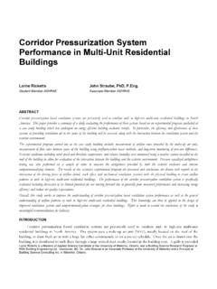
6 Use self-tapping sheet metal screws to fasten unit tothe curb and equipment support throughholes , coil, and/or gas connections canbe made at this caution to avoid damaging exhaust fanwhen installing supply InstallationIllustration shows the complete wiredinstallation. Note that the electrical powercable for the exhaust fan is routed throughthe side breather tube. The cable should beof sufficient length to allow the fan to hingeopen to the point where the restrainingcables support the fan. Exhaust FanElectrical Cable3 BSquare CurbFootprintEquipmentSupportFootprintC LC LC LAA/2A/2 ARoofOpeningC*RectangularCurbFootprintC LC LAA/2 ARoofOpeningA/2C*C*C- Determine equal dimension for these 3 locations ( varies per curb size)SupplyDuctworkby OthersSealantDuctwork with ductadapter installedInstallation with Down Discharge Step 1 Roof OpeningDetermine the center of the supply duct roofopening.
7 The chart below shows the maximumrecommended roof opening dimensions. Thesesizes can be smaller based on codes andductwork Size#1#2#3A - Max Roof Open. "35"47"Supply Duct CL toB -761/2"811/2"881/2" Equip. Support CL Before beginning this installation:When locating this unit , make sure that there is room toaccess the unit from all sides. The inlet must be located atleast 10 feet away from any exhaust vents. If this unit isdirect fired gas without insulation, it has a 6 clearancetolerance to combustibles on all sides, top, and 2 Install Roof Curb and Equipment SupportFor square curbs, center curb over roofopening as shown in first installation diagram atleft.
8 For rectangular curbs, center curb on 3 sides ofroof opening, as shown in second installationdiagram, by determining C dimension (varies per unit /curb size ). For either installation, level the curb and shim if necessary. Attach curb to roof and flash in equipment support is needed, refer to chart instep 1 for dimensional location based on KSUunit size. Attach to roof in the same manner asthe curb. Remove metal cover, flash to woodennailer and reinstall cover (see pg. 2). Step 3 Install DuctworkThe chart at left shows the duct sizes andstraight lengths recommended for optimalperformance (AMCA Publication 201-90). Usingduct sizes less than the recommended lengthswill affect fan performance.
9 Good duct practicesshould be followed for the remaining use of a duct adapter with the supply duct isstrongly recommended to properly align theductwork with the supply fan discharge. Theduct adapter is only a guide and is not intendedto be used as support for the ductwork. Step 4 Apply SealantBefore installing fan, apply a sealant around the perimeter of the supply duct adapter toisolate the fan and minimize vibration. For Installations usingrectangular curb:For Installations using square curb and equipment support:4 Recommended Supply Ductwork SizesStraight BlowerDuctDuctSizeSizeLength10813 x 1337 10913 x 1337"11014 x 1447"11216 x 1654"11520 x 2068"11824 x 2481"12026 x 2696"Supply UnitLifting Lugs(4 places)Step 5 Install Supply UnitUse a crane and a spreader barhooked to the factory lifting lugs (asshown in the diagram) to lift andcenter the KSU unit on the curb andequipment support.
10 Use self-tapping sheet metal screws tofasten unit to the curb andequipment support through , coil, and/or gasconnections can be made at InstallationIllustration shows the completeinstallation of a downblast with Horizontal Discharge6 INTAKEDISCHARGEDISCHARGEINTAKEAE quipmentSupportFootprintC LC LEquipmentSupportFootprintC LACurbFootprintEquipmentSupportFootprint C LC LC L( )Roof mounted with weatherhood, mounted on twoequipment supports. Ductwork is attached to dischargecollar with rubber boot transition.( )Shown as an indoor hanging installation withintake and discharge ductwork installed. (Hanging support structure for unit is by others).