Transcription of H SR103AM - OMRON
1 SR103AM . R. C US. Conforms to EN60204-1, EN954-1, VDE 0113-1. UL and C-UL listed, BG approved H. safety monitoring relays SR103AM . Dual Channel Safety Monitoring Relay Power requirements the Outputs the SR103AM has Monitored manual or auto- SR103AM will accept 3 N/O outputs to route power to matic/manual reset modes are 24 VAC/DC, 115 VAC, or the coils of power contactors, available on the SR103AM . 230 VAC plus 1 N/C auxiliary output for Monitored manual reset re- signaling purposes quires closure of the reset Inputs the SR103AM will circuit followed by opening of accept single or dual N/C inputs External Device Monitoring the circuit. Reset occurs when or dual inputs from a light (EDM) is provided with a N/C circuit is opened. Auto reset curtain (see SR102AM for loop between S11/S12 and S21 requires only closure of the application wiring for a light on the SR103AM reset circuit as reset occurs curtain) when circuit is closed.
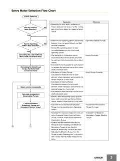
2 Go to the Engineering Guide A For in-depth information on safety standards and use. USA Tel. 1/888/510-4357 UK Tel. +44 (0) 1395-273-209 Japan Tel. +81-466-22-1132 For the Latest Information R. Canada Tel. 1/800/221-7060 Europe Tel. +49 (0) 5258-938-776 China Tel. +86-21-5836-7708 On the Internet: H12 Singapore Tel. +65-648-44-001 E-mail: SR103AM . Application See the SR102AM for wiring to a light curtain 24 VAC/DC, 110 VAC, 230 VAC. K1 (AUX). START L1 L2 L3. MOMENTARY K2 (AUX). PUSH. EB SERIES BUTTON. LATCHING STOP. E-STOP MOMENTARY RESET. BUTTON PUSH. BUTTON. MOMENTARY. PUSH. GUARD A1 S11 S21 S12 S14 13 23 33 41 BUTTON. CLOSED. Power supply Relay control and K1. 11 21 33 (S11 = 24 V) fault monitoring +. K2 K2. 12 22 34. CONTACT. + PROTECTION. T5009. INTERLOCK. K1 THERMAL. CUT OUT H.
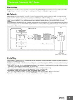
3 SR103AM . SWITCH. M. safety monitoring relays A2 S10 S13 14 24 34 42. FUSE FUSE. K1 K2. For a full explanation of the circuit operating principle and fault detection, see Common Circuit Examples in the Engineering Section of this catalog. Output Contact Terminal Pin Assignments Arrangements 14 S12 A1 13. 24 S13 S11 23. 34 S10 S14 33. 42 A2 S21 41. Terminal Connections 13 23 33 41. A1 S13 S11 S21. SAFETY SAFETY SAFETY AUXILIARY. INPUT #1 INPUT #2 EDM AND. SUPPLY OUTPUT 1 OUTPUT 2 OUTPUT 3 SIGNALING. N/C N/C RESET. N/O N/O N/O N/C. A2 S10 S12 S12. 14 24 34 42. For the Latest Information USA Tel. 1/888/510-4357 UK Tel. +44 (0) 1395-273-209 Japan Tel. +81-466-22-1132. On the Internet: Canada Tel. 1/800/221-7060 Europe Tel. +49 (0) 5258-938-776 China Tel. +86-21-5836-7708 R. E-mail: Singapore Tel.
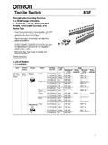
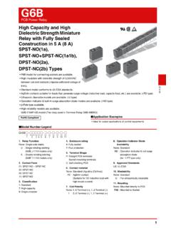
4 +65-648-44-001 H13. SR103AM . Block Diagram A1 S11 S21 S12 S14 13 23 33 41. Relay control and Power supply fault monitoring (S11=24V). +. K1. Pin assignment UB A1 A2. +. DC +U B 0V. AC L1 N K2. A2 S10 S13 14 24 34 42. H. Dimensions mm/in. safety monitoring relays SR103AM . 114 99. 35. DIN RAIL MOUNTING. Go to the Engineering Guide A For in-depth information on safety standards and use. USA Tel. 1/888/510-4357 UK Tel. +44 (0) 1395-273-209 Japan Tel. +81-466-22-1132 For the Latest Information R. Canada Tel. 1/800/221-7060 Europe Tel. +49 (0) 5258-938-776 China Tel. +86-21-5836-7708 On the Internet: H14 Singapore Tel. +65-648-44-001 E-mail: SR103AM . Specifications Electrical All Models SR103AM01 SR103AM02 SR103AM03. Power Supply: 10%, 50-60 Hz 24 VAC/DC 115 VAC 230 VAC. Power Consumption: Approx.
5 1 VA. Safety Inputs: 1 N/C or 2 N/C or 2 solid state (light curtain). Max Input Resistance: 800 Ohms per channel Outputs: 3 N/O + 1 N/C auxiliary Output Rating AC: Inductive AC-15, 3 A/230 VAC. Output Rating DC: Inductive DC-13, 2 A/24 V. Min Switched Current/Voltage: 10 mA/10 V. Impulse Withstand Voltage: 2500 V. Max Drop-Out Time: 12 ms (75 ms by removing supply voltage). Max Output Fuse: 6 A quick-acting or 4 A slow-acting Reset Mode: Monitored manual (S11-S21) or automatic/manual (S12-S21). Contactor Monitoring: N/C loop S11/S12-S21. Mechanical Mounting: 35 mm ( in.) DIN rail Case Material: Fiber-filled Polyamide H. Max Wire Size: 1 x mm2 (14 AWG) stranded safety monitoring relays Weight: 230 g ( oz.). Color: Red External Switches: None Indication: Green = K1 Closed, Green = K2 Closed Mechanical Life: 1 x 10⁷ operations Environmental Enclosure Protection: IP20 terminals, IP40 (NEMA 1) housing Operating Temperature: 24 VAC/DC: -15 to 40 C (5 to 104 F).
6 115/230 VAC: -15 to 40 C (5 to 104 F). Humidity: 93% RH at 104 C (219 F). Compliance Standards: EN 60204-1, EN 954-1, VDE 0113-1. Approvals/Listings: CE marked for all applicable directives, BG, UL and C-UL. Safety Category: Cat. 4 per EN954-1 (SR103 internal operation). Specifications are subject to change without notice. Note: The safety contacts of the STI switches are described as normally closed (N/C) , with the guard closed, actuator in place, and the machine able to be started. Ordering Model Supply Inputs Outputs Auxiliary Part No. SR103AM01 24 VAC/DC 2 N/C 3 N/O 1 N/C 44510-1031. SR103AM02 115 VAC 2 N/C 3 N/O 1 N/C 44510-1032. SR103AM03 230 VAC* 2 N/C 3 N/O 1 N/C 44510-1033. *230 VAC units are available on special order. Minimum quantities may apply. For the Latest Information USA Tel.
7 1/888/510-4357 UK Tel. +44 (0) 1395-273-209 Japan Tel. +81-466-22-1132. On the Internet: Canada Tel. 1/800/221-7060 Europe Tel. +49 (0) 5258-938-776 China Tel. +86-21-5836-7708 R. E-mail: Singapore Tel. +65-648-44-001 H15.