Transcription of Temperature Controllers E5CSL/E5CWL/E5EWL - Omron
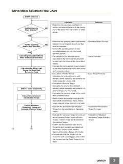
1 1 New ProductTemperature ControllersE5 CSL/E5 CWL/E5 EWL The Simple and New Temperature Controller is Released that Easily Achieves the Temperature Control. Easy to Read (Character Height E5 CSL: mm, E5 CWL: mm (PV), E5 EWL: 20 mm (PV)). Depth beyond front panel: Only 60 mm. Fewer parameters for simple setup. Faster sampling at 250 :Refer to Precautions on page 9. Main I/O FunctionsModel Number StructureModel Number Legend1. Control OutputR: Relay output: 250 VAC, 3 AQ: Voltage output (for driving SSR): 12 VDC, 21 mA2. Sensor typeTC: Thermocouple (K, J, T, R, or S)P: Platinum resistance thermometer (Pt100)1. Control OutputR: Relay output: 250 VAC, 3 AQ: Voltage output (for driving SSR): 12 VDC, 21 mA2. Alarm1: Relay output: 250 VAC, 1 A (resistive load)3.
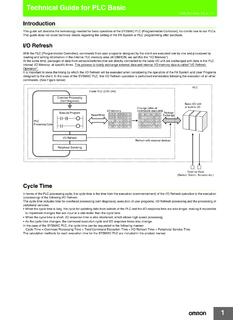
2 Sensor typeTC: Thermocouple (K, J, T, R, or S)P: Platinum resistance thermometer (Pt100)1. Control OutputR: Relay output: 250 VAC, 3 AQ: Voltage output (for driving SSR): 12 VDC, 21 mA2. Alarm1: Relay output: 250 VAC, 1 A (resistive load)3. Sensor typeTC: Thermocouple (K, J, T, R, or S)P: Platinum resistance thermometer (Pt100)48 48 mmE5 CSL48 48 mmE5 CWL48 96 mmE5 EWLS ensor Inputs Thermocouple inputs Pt inputsIndication Accuracy Thermocouple input: of PV Pt input: of PVSampling Period 250 msControl Output Relay output Voltage output (for driving SSR)Alarm Outputs OneSingle Display: E5 CSLDual Display: E5 CWL 4-digit DisplayDual Display: E5 EWL4-digit DisplayE5 CSL/E5 CWLE5 EWL*E5 CWL/E5 EWL only12E5 CSL-@@213E5 CWL-@1@213E5 EWL-@1@E5 CSL/E5 CWL/E5 EWL2 Ordering InformationE5 CSLE5 CWLE5 EWLA ccessories (Order Separately)Terminal CoverFront Panel (for E5 CSL/E5 CWL)Note.
3 Front Panel accessory is required to attach the Y92A-48B or Front Panel accessory is only the does not include the plastic :E5 CWL/E5 EWL onlySizePower supply voltageInput typeAlarm outputControl outputModel1/16 DIN 48 48 60(W H D)100 to 240 VACT hermocoupleNoneRelay outputE5 CSL-RTCR esistance thermometerE5 CSL-RPThermocoupleVoltage output (for driving SSR)E5 CSL-QTCR esistance thermometerE5 CSL-QPSizePower supply voltageInput typeAlarm outputControl outputNew model1/16 DIN 48 48 60(W H D)100 to 240 VACT hermocouple1 Relay outputE5 CWL-R1 TCResistance thermometerE5 CWL-R1 PThermocoupleVoltage output (for driving SSR)E5 CWL-Q1 TCResistance thermometerE5 CWL-Q1 PSizePower supply voltageInput typeAlarm outputControl outputNew model1/8 DIN 48 96 60(W H D)
4 100 to 240 VACT hermocouple1 Relay outputE5 EWL-R1 TCResistance thermometerE5 EWL-R1 PThermocoupleVoltage output (for driving SSR)E5 EWL-Q1 TCResistance thermometerE5 EWL-Q1 PModelE53-COV19 ModelE53-COV20 ModelRemarksY92F-45 Use this Adapter when the Front Panel has already been prepared for the Only black is available. Order Use for E5 CSL/E5 CWL only. Provided with E5 Use for E5 EWL only. Provided with supply voltage100 to 240 VAC, 50/60 HzOperating voltage range85% to 110% of rated supply voltagePower VASensor inputModels with thermocouple inputsThermocouple: K, J, T, R, or SModels with platinum resistance thermometer inputsPlatinum resistance thermometer: Pt100 Control outputRelay outputSPST-NO, 250 VAC, 3 A (resistive load), electrical life: 100,000 operations, minimum load: 5 V, 10 mAVoltage output(for driving SSR)Output voltage: 12 VDC 25%/ 15% (PNP), max.
5 Load current: 21 mA, with short-circuit protection circuitAlarm output (See note.)SPST-NO, 250 VAC, 1 A (resistive load), electrical life: 100,000 operations, minimum load: 5 V, 10 mAControl methodON/OFF control or 2-PID control (with auto-tuning)Setting methodDigital setting using front panel keysIndication method7-segment digital display and individual indicatorsCharacter height: E5 CSL: mm, E5 CWL: mm (PV), E5 EWL: 20 mm (PV)Other functionsTemperature input shift, run/stop, protection functions, operating Temperature 10 to 55 C (with no icing or condensation)Ambient operating humidity25% to 85%Storage Temperature 25 to 65 C (with no icing or condensation)E5 CSL/E5 CWL/E5 EWL3 Input RangesModels with Thermocouple InputsDefault setting: 0 Applicable standards (K, J, T, R, S).
6 JIS C1602-1995 and IEC 60584-1 Models with Resistance Thermometer InputsDefault setting: 8 Applicable standards (Pt100): JIS C1604-1997 and IEC 60751 Alarm TypesSelect alarm types out of the 11 alarm types listed in the following :Alarms with a Standby SequenceThe alarm is blocked until the first safe-state is reached. Unwanted alarm during start-up are prevented. Example: Deviation Lower Limit Standby Sequence ONThe standby sequence is cleared when the alarm OFF condition has been standby sequence is started again when any of the following conditions is met. Operation is started (power is turned ON or operation is switched from stop to run). The alarm value is changed. The Temperature input offset is changed. The set point is ( Temperature input)Set valueInput typeRange C FTC input0K 200 to 1,300 300 to 2,3001 to to 100 to 850 100 to 15003 to to 200 to 400 300 to 7005 to to 0 to 1,700 0 to 3,0007S 0 to 1,700 0 to 3,000 Model( Temperature input)Set valueInput typeRange C FPt input8Pt100-200 to 850-300 to to to typePositive alarm value (X)Negative alarm value (X)0No alarmOutput OFF1 Deviation upper/lower limitAlways ON2 Deviation upper limit3 Deviation lower limit4 Deviation upper/lower rangeAlways OFF5 (See note.)
7 Deviation upper/lower limit standby sequence ONAlways OFF6(See note.)Deviation upper limit standby sequence ON7(See note.)Deviation lower limit standby sequence ON8 Absolute value upper limit9 Absolute value lower limit10(See note.)Absolute value upper limit standby sequence ON11(See note.)Absolute value lower limit standby sequence ON12 Do not sequence clearedAlarm valueAlarm with standby sequenceProcess valueTimeAlarm without standby sequenceAlarm hysteresis (always C/ F)E5 CSL/E5 CWL/E5 EWL4 CharacteristicsNote: indication accuracy of K and T thermocouples at a Temperature of 100 C max. is 2 C 1 digit maximum. The indication accuracy of the R and S thermocouples at a Temperature of 200 C max. is 3 C 1 digit , and S sensors: C/ max.
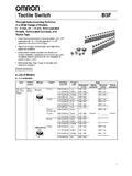
8 (100 max.) electromagnetic environment (EN/IEC 61326-1 Table 2)Electrical Life Expectancy Curve for Relays (Reference Values)Indication accuracyThermocouple: (See note 1.)( of indicated value or 1 C, whichever is greater) 1 digit resistance thermometer:( of indicated value or 1 C, whichever is greater) 1 digit of temperatureR and S thermocouple inputs:( 1% of PV or 10 C, whichever is greater) 1 digit , J, and T thermocouple inputs:( 1% of PV or 4 C, whichever is greater) 1 digit resistance thermometer inputs:( 1% of PV or 2 C, whichever is greater) 1 digit of voltageInfluence of EMS. (at EN61326-1) to (in units of ) C/ FProportional band (P) to (in units of ) C/ FIntegral time (I)0 to 3999 s (in units of 1 s)Derivative time (D)0 to 3999 s (in units of 1 s)Control , 1 to 99 s (in units of 1 s)Alarm setting range 1999 to 9999 (decimal point position depends on input type)Sampling period250 msAffect of signal source resistanceThermocouple: C/ max.
9 (100 max.) (See note 2.)Platinum resistance thermometer: C/ max. (10 max.)Insulation resistance20 M min. (at 500 VDC)Dielectric strength2,300 VAC, 50 or 60 Hz for 1 min (between terminals with different charge)Vibration resistanceMalfunction10 to 55 Hz, 20 m/s2 for 10 min each in X, Y, and Z directionsDestruction10 to 55 Hz, 20 m/s2 for 2 hrs each in X, Y, and Z directionsShockresistanceMalfunction100 m/s2 min., 3 times each in X, Y, and Z directionsDestruction300 m/s2 min., 3 times each in X, Y, and Z directionsWeightE5 CSL/E5 CWLC ontroller: Approx. 100 g, Mounting Bracket: Approx. 10 gE5 EWLC ontroller: Approx. 150 g, Mounting Bracket: Approx. 10 gDegree of protectionFront panel: IP50 Rear case: IP20, Terminals: IP00 Memory protectionNon-volatile memory (number of writes: 100,000 times)Conformed standardsEN61326-1 (See note 3.)
10 , EN61010-1, IEC61010-1 VDE0106 Part 100 (Finger protection), when the terminal cover is Enclosure:EN55011 Group1 Class AEmission AC Mains:EN55011 Group1 Class AImmunity ESD:EN61000-4-2 Immunity RF-interference:EN61000-4-3 10 V/mImmunity Conducted Disturbance:EN61000-4-6 3 VImmunity Burst:EN61000-4-4 Immunity Surge:EN61000-4-5 Immunity Voltage Dip/Interrupting: EN61000-4-11 Contact current (A)250 VAC, 30 VDC resistive loadNo. of operations (x 104)10050301053101 2 34 5E5 CSL/E5 CWL/E5 EWL5 External Connections A voltage output (control output) is not electrically insulated from the internal circuits. When using a grounding thermocouple, do not connect any of the control output terminals to ground. If the control output terminals are connected to ground, errors will occur in the measured Temperature values as a result of leakage + ABBPt inputInput power supply: 100 to 240 VAC, 50/60 HzDO NOTUSEC ontrol output+ TC input1 Control Output Relay output: 250 VAC, 3 A (resistive load) Voltage output (for driving SSR): 12 VDC, 21 mA2345910E5 CSLI nput power supply: 100 to 240 VAC, 50/60 HzControl Output Relay output: 250 VAC, 3 A (resistive load) Voltage output (for driving SSR): 12 VDC, 21 mAPt input Alarm Output Relay output: 250 VAC, 1 A (resistive load) DO NOT USE TC input + A B B + 1 2 3 4 789106 Control output E5 EWL+ ABBPt inputAlarm Output Relay output: 250 VAC, 1 A (resistive load)Input power supply.