Transcription of HAND SOLDERING TRAINING COURSE - Almit
1 1 HAND SOLDERING TRAINING COURSE2 Aim Review the whole SOLDERING process to improve SOLDERING quality. Aim for high first time pass rates. How to approach SOLDERING Regardless of what product an electronic assembler makes, we can say they really only make solder joints. It s the process that brings everything electrical together. Every joint should be made with care. If not then you may be able to weed out the poorest during inspection/test but some will pass and they will be the weakest bit of the product and will fail in service, especially in automotive products where temperature & vibration can be considerable In service failures are expensive to repair and always have other negative effects on the business. All customers know the solder joint is potentially the weakest part of the is SOLDERING ? solder Workstation5. SOLDERING Process6.
2 Inspection + Training4 Formation of a metal to metal joint using solder . The joint is made by alloy formation of base metal and solder . In SOLDERING , there are three key elements :Heat , solder , Flux , they are all cored solder wire is used for hand What is SOLDERING ?What is SOLDERING ?51-2. Flux Function What does it do?Remove oxideRemove metal oxide to support wettability of surface tensionReduce surface tension of solder to allow it to spread onto finishMake smooth surface finish of solder and prevent solder from re-oxidationCoat metal surface to prevent from solderWhat is SOLDERING ?During SOLDERING a chemical reaction takes place. The flux removes all the surface tarnish leaving clean metal solder WettingNot wettedNot soldered (dry joint)WettedsolderedCheck the wetting angleCheck the wetting angleWhat is SOLDERING ?No goodNo goodGood71-4.
3 Melting and Diffusion Alloy is formed by melting and diffusion of metals Tin and copper alloy togetherAlloy layer in good conditionThin and even thickness of alloy layerDiffusionMelting Alloy layerWhat is SOLDERING ?It takes a certain amount of time to create theperfect solder joint. Too slow a process can damage pcb/components and too fast will not create a sound solder WireSolder typeDiameterSolder ~ Always confirm before use. (Use of different solders and diameters depends on the products being soldered)Cored solder WireAlloy CompositionSn60,Sn50,Sn45 PbFree Alloy(Sn-Ag-Cu)9 FLUX = Mix of resins, activators, wetting agents & corrosion inhibitorsSolder metal2-2. Construction of Cored SolderCored solder WireAttentionSn-Pb seriesPbFree series10 solder Alloy Most use Sn60/Pb40or Sn62/Pb36/Ag2 or LEAD FREE Flux Type. No-Clean RMA ( Almit KR19 SH) Flux residues are safe to leave on pcb.
4 They will not cause corrosion or electrical breakdown of cct during its lifetime. Flux % 1,2 or 3. Higher flux % makes SOLDERING easier but can leave more flux residue which can make solder joint look cosmetically dirty Wire Diameter Select the right one for the job. Reel Size Generally 500g2-3. solder Wire VariablesCored solder Wire11 Easy feeding for continuous feeding for continuous suitable forcontinuous suitable forcontinuous Handling method for cored solder wireCored solder Wire50 100mm2 4 123-1. SOLDERING IronsSoldering stationTemperature setting differs depending on to check the temperature before starting the holderSponge for cleaning SOLDERING iron IronSoldering IronsThe SOLDERING iron is critical to good SOLDERING . It must provide all the heat to heat up the joint which in turn must heat up the solder wire/flux133-2.
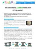
5 SOLDERING IronsDifferences in power capacity, size and one depending on the type of work . 80 WWeller better for Pb Free or large jointsIron tip Iron tip shape is different for each correct iron tip for part of SOLDERING ironCeramic heaterWeak to impact / Irons14 Pen-holder typeFor normal operation Pen-holder typeFor normal operation Grip typeFor large componentGrip typeFor large component3-3. How to hold SOLDERING IronSoldering Irons153-4. How the tip is madeThe most important part of the SOLDERING iron is the main part of the tip is made of copper. To extend the lifetime of the tip, it is iron coated .Before the iron is added the copper is nickel plated. The non wettable part of the tip is chrome plated. The chrome stops the solder flowing up the tip. The tip is pre-tinned with lead free coating: ca. 10 - 20 mIron coating: ca.
6 150 - 300 mChrome Coating:ca. 3 - 6 mSoldering Irons16 Use water or Tip CleaningFluid to not use to much or to little. Keep tip tinned with Tip Cleaning sponge in V. Use the cut part to cleanIf tip not properly cleaned this can cause flux splatter, solder waste and poor heat conduction to joint area which can cause need to increase the number of cleaning times when using Pb Free tip not properly cleaned this can cause flux splatter, solder waste and poor heat conduction to joint area which can cause need to increase the number of cleaning times when using Pb Free How to clean SOLDERING IronSoldering Irons17 Temperature LossTemperature back to normalToo much waterNeed longer time if temperature reduce too conditionTo start operation after temperature back to normal and range of operation C C Ex 3-6.
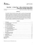
7 Temperature when cleaningSoldering Irons183-7. Temperature Stability C450 80 Watt400 50 Watt350 300 250 ||||||0 1020304050t/sEach time a solder joint is made the heat in the SOLDERING iron is depleted especially if joints are made quickly SOLDERING Irons193-8. solder Iron Tip ConditionSoldering ironsThis tip has soldered 1000 joints. The tinned area is still shiny and is no charred flux adhering to it. Only use the tinned area to heat up joint area. It helps the heat to be transferred quickly/consistently. Using thenone tinned area of the iron will cause SOLDERING problemsThis tip has soldered 20000 joints. Still in perfect condition203-9. solder Iron Tip Condition 2 SOLDERING ironsThe tinned area is dull and inconsistent and there is lots of charred flux adhering to it. The ability of this tip to transfer heat to the solder joint is significantly impaired by its poor SOLDERING Workstation Ventilation duct Check temperature Sponge.
8 Check the water or cleaning fluid qtyIronFix the holder and check the iron the Sn%, type, diameterWorking tableAlways keep in clean note of solder ,etcSoldering Workstation224-2. Correct posture when solderingCorrectBadAbove Not suitable. Poor position for back pain . Flux fumes could be WorkstationMust have clear view of work. Feeding in wire and iron movementmust be smooth and Considerations to create best workstation ESD Bench Must be ESD safe to eliminate static Keep it clean/tidy Lighting Keep it as natural as possible. Fume Extraction Keep the filters clean Iron/wire Position Must be positioned to allow smooth access to solder joint area. Work Jig Must be free from flux residues etcSoldering Workstation244-4. Summary so Check the solder type Check the solder iron Check the cleaning sponge SOLDERING posture255-1.
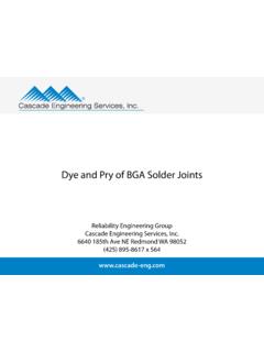
9 SolderingpreparationheatUse iron tip to heat the SOLDERING solderMelt properlyPull out solderPull out iron tip5 step methodsolderironSolder will not alloy if the parts and solder are not fully heated. The SOLDERING iron is not just to heat and melt the solder , but to heat the part being SolderingpreparationHeat up to @ over 100 C. May take @ 2 secsInsert solder to hot joint area. Flux melts and covers joint. Flux helps melt solder and it flows over clean pad/lead. solder area @ 230-240 out solderPull out iron tip5 step methodsolderironSoldering275-3. Heating Large JointHandling method of iron tip differs by shape of iron tip body to heat up the joint, but the area in contact with the joint must be tinned and large terminal/area by moving iron tipSoldering285-4. solder Wetting o goodSolder wets to lead and and shiny holes, no wetting to solder QuantityNo goodOKNo goodExcess amount Lack of solderApply correct solder amount.
10 No good if too much or too to confirm whether solder is joint is weak, and leads to solder Quantity and Surface Condition 1Sn60Pb FreeSmall amountLarge amountSoldering31Sn60Pb Free5-7. solder Quantity and Surface Condition 2 NGNGS oldering32 What is the appropriate temperature for SOLDERING ?Joint area temperature = The of solder alloy+40~50 Degree C Sn60% solder (190 Degree C) +40~50 Degree C =230~240 Degree C However the iron will be set much hotter @350-450 C The hotter the iron the faster the joint can be made providing the heat transfer from it is good. Must try to heat up both/all parts to be soldered at the same time. If it is difficult to do this then evaluate special solder iron tips. Heating up more than needed, will cause overheating defects. Using a very hot iron will increase the risk of SOLDERING defects and component damage.