Transcription of Hardware Manual TSP100 - starmicronics.com
1 Hardware ManualFederal Communications CommissionRadio Frequency InterferenceStatementThis equipment has been tested and found to comply with the limits for a Class A digital device, pursuant to Part 15of the FCC Rules. These limits are designed to provide reasonable protection against harmful interference when theequipment is operated in a commercial environment. This equipment generates, uses and can radiate radio frequencyenergy and, if not installed and used in accordance with the instruction Manual , may cause harmful interference toradio communications. Operation of this equipment in a residential area is likely to cause harmful interference inwhich case the user will be required to correct the interference at his own compliance with the federal Noise Interference Standard.
2 This equipment requires a shielded statement will be applied only for the printers marketed in ofThe Canadian Department of CommunicationsRadio Interference RegulationsThis digital apparatus does not exceed the Class A limits for radio noise emissions from digital apparatus set out inthe Radio Interference Regulations of the Canadian Department of pr sent appareil num rique n met pas de bruits radio lectriques d passant les limites applicables aux appareilsnum riques de la classe A prescrites dans le R glement sur le brouillage radio lectrique dict par le minist re desCommunications du above statement applies only to printers marketed in s Declaration of ConformityEC Council Directive 89/336/EEC of 3 May 1989 This product, has been designed and manufactured in accordance with the International Standards EN 61000-6-3 / 2001 and EN 55024 / 1998, following the provisions of the Electro Magnetic Compatibility Directive of theEuropean Communities as of May Council Directive 73/23/EEC and 93/68/EEC of 22 July 1993 This product, has been designed and manufactured in accordance with the International Standards EN 60950-1,following the provisions of the Low Voltage Directive of the European Communities as of above statement applies only to printers marketed in acknowledgmentsTSP100: Star Micronics Co.
3 , All rights reserved. Reproduction of any part of this Manual in any form whatsoever, without STAR s expresspermission is forbidden. The contents of this Manual are subject to change without notice. All efforts have been made to ensure the accuracy of the contents of this Manual at the time of going to , should any errors be detected, STAR would greatly appreciate being informed of them. The above notwithstanding, STAR can assume no responsibility for any errors in this Manual . Copyright 2005 Star Micronics Co., OF CONTENTS1. Unpacking and Installation .. 11-1. Unpacking .. 12. Parts Identification and Nomenclature .. 23. Setup .. 53-1. Connecting the USB Cable to the Printer .. 53-2. Connecting to a Peripheral Unit.
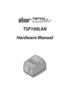
4 63-3. Loading the Roll Paper .. 73-4. Connecting the USB Cable to the PC .. 103-5. Installing the Printer Software .. 103-6. Connecting the Power Cord .. 113-7. Turning Power On .. 124. Attaching the Accessories .. 134-1. Attaching the Holder Plate .. 134-2. Attaching the Rubber Feet .. 144-3. Switch Blind Installation .. 155. Thermal Roll Paper Specification .. 166. Control Panel and Other Functions .. 176-1. Control Panel .. 176-2. Errors .. 176-3. Self-Printing .. 197. Preventing and Clearing Paper Jams .. 207-1. Preventing Paper Jams .. 207-2. Removing Paper Jam .. 207-3. Releasing a Locked Cutter (Auto Cutter Mode only) .. 218. Periodical Cleaning .. 238-1. Cleaning the Thermal Head.
5 238-2. Cleaning the Paper Holder .. 239. Peripheral Unit Drive Circuit .. 2410. Specifications .. 2610-1. General Specifications .. 2610-2. Auto Cutter Specifications .. 2710-3. Interface .. 2710-4. Electrical Characteristics .. 2710-5. Environmental Requirements .. 2710-6. Reliability .. 28 Please access the following the latest revision of the Manual . 1 1. Unpacking and Installation1-1. UnpackingAfter unpacking the unit, check that all the necessary accessories are included in the 1-1 UnpackingIf anything is missing, contact the dealer where you bought the printer and ask them to supplythe missing part. Note that it is a good idea to keep the original box and all the packing materialsjust in case you need to pack the printer up again and send it somewhere at a later roll holderHolder plateSwitch blindUSB cablePower cordRubberfeetCD-ROMS etup sheetRoll paperScrewsFerrite core 2 2.
6 Parts Identification and NomenclatureAuto Cutter ModelCover open leverPull this lever in thedirection of the arrow toopen the printer panelFeatures LED indicators to indicateprinter status and switches tooperate the switchUsed to turn on/offpower to the connectorFor connection of thepower drive connectorConnects to peripheralunits such as cash draw-ers, not connect this to connectorFor connection to ahost coverOpen this cover to load orreplace paper. 3 Tear Bar ModelCover open leverPull this lever in thedirection of the arrow toopen the printer connectorFor connection of thepower drive connectorConnects to peripheral unitssuch as cash drawers, not connect this to connectorFor connection to ahost coverOpen this cover to load orreplace panelFeatures LED indicatorsto indicate printer statusand switches to operatethe switchUsed to turn on/offpower to the printer.
7 4 Choosing a place for the printerBefore actually unpacking the printer, you should take a few minutes to think about whereyou plan to use it. Remember the following points when doing this. Choose a firm, level surface where the printer will not be exposed to vibration. The power outlet you plan to connect to for power should be nearby and unobstructed. Make sure that the printer is close enough to your host computer for you to connect thetwo. Make sure that the printer is not exposed to direct sunlight. Make sure that the printer is well away from heaters and other sources of extreme heat. Make sure that the surrounding area is clean, dry, and free of dust. Make sure that the printer is connected to a reliable power outlet.
8 It should not be on thesame electric circuit as copiers, refrigerators, or other appliances that cause powerspikes. Make sure that the room where you are using the printer is not too Shut down your equipment immediately if it produces smoke, a strange odor, or unusualnoise. Immediately unplug the equipment and contact your dealer for advice. Never attempt to repair this product yourself. Improper repair work can be dangerous. Never disassemble or modify this product. Tampering with this product may result ininjury, fire, or electric shock. 5 3. Setup3-1. Connecting the USB Cable to the PrinterAffix the ferrite core onto the USB interface cable and pass the cable through the cable supportas shown.
9 Then, connect the USB interface cable to the :The dialog shown below may appear on your PC screen if your PC is running Windows98 or Me, and if you turn ON the power of the printer for the first time while the PC andthe printer are connected with the USB cable. In this case, refer to the software manualon the CD-ROM, in the following directory: Documents folder. 6 3-2. Connecting to a Peripheral UnitYou can connect a peripheral unit to the printer using a modular plug. The following describeshow to install the ferrite core and make the actual connection. See Modular plug on page 24for details about the type of modular plug that is required. Note that this printer does not comewith a modular plug or wire, so it is up to you to obtain one that suits your sure that the printer is turned off and unplugged from the AC outlet and that the computeris turned off before making connections.
10 (1) Connect the peripheral drive cable to the connector on the rear panel of the not connect a telephone line into the peripheral drive connector. Failure to observe this mayresult in damage to the , for safety purposes, do not connect wiring to the external drive connector if there is a chanceit may carry peripheral voltage. 7 3-3. Loading the Roll PaperBe sure to use roll paper that matches the printer s using a paper roll with an mm width, install the paper roll holder as described on thefollowing open leverRoll paper1) Push the cover open lever, and open theprinter ) While observing the direction of the roll,set the paper roll into the hollow, and pullon the leading edge of the paper towardyou.