Transcription of HEAT PUMP INSTALLATION INSTRUCTIONS
1 heat PUMP INSTALLATION INSTRUCTIONSHEAT PUMP SAFETYTa b l e o f C o n t e n tsHEAT PUMP REQUIREMENTS ..2 Tools and Parts ..2 System Requirements ..2 Electrical Requirements ..3 INSTALLATION INSTRUCTIONS ..3 Inspect Shipment ..3 Connect Refrigerant Lines ..3 Make Electrical Connections ..5 Complete of Operation ..9 ADJUSTING DEFROST SYSTEM ..9 SYSTEM MAINTENANCE ..10 ASSISTANCE OR SERVICE ..10 Accessories ..10 WARRANTY ..1146922G003 You can be killed or seriously injured if you don'timmediately follow can be killed or seriously injured if you don'tfollow safety messages will tell you what the potential hazard is, tell you how to reduce the chance of injury, and tell youwhat canhappen if the INSTRUCTIONS are not safety and the safety of others are very have provided many important safety messages in this manual and on your appliance.
2 Always read and obey allsafety is the safety alert symbol alerts you to potential hazards that can kill or hurt you and safety messages will follow the safety alert symbol and either the word DANGER or WARNING. These words mean:2 INSTALLATION REQUIREMENTST hese INSTRUCTIONS are intended as a general guide only and donot supersede any national or local codes in any way. Theinstallation must comply with all state, and local codes as well asthe National Electrical Code. The heat pump is designed and approved for outdoor useonly. The heat pump must be installed with no duct work in theairstream. The outdoor fan is not designed to operate againstany additional static and PartsAssemble the required tools before starting INSTALLATION .
3 Read andfollow the INSTRUCTIONS provided with any tools listed Needed:Parts Needed:Check local codes and HVAC supplier. Check existing electricalsupply, and read Electrical Requirements, LocationRequirements, System Requirements and ConnectRefrigerant Lines. System RequirementsHeat pump system matches are derived from actual laboratorytesting of matched systems. It is recommended that onlymatching equipment be used to ensure proper operation andefficient performance. The designed system matches are listed in the heat pumpunit specification sheets and on the heat pump refrigerantcharging INSTRUCTIONS located on the back of the serviceaccess panel. Refrigerant charging INSTRUCTIONS include a list of matchingindoor equipment with the proper orifice size and amount ofrefrigerant charge required.
4 This heat pump has been factory charged with a quantity ofrefrigerant (R22) sufficient for a matched indoor coil and amaximum 20 ft of refrigerant System Orifice Check the indoor coil orifice to see whether it matches therequired orifice for the indoor coil and heat pumpcombination being installed. Refer to the refrigerant charge label located on the inside ofthe heat pump access panel for the correct orifice sizerequired. Replace the orifice with the correct size if this size is notalready installed in the indoor coil. INSTRUCTIONS for Requirements This heat pump is designed to be located outdoors withsufficient clearance for free entrance to the inlet anddischarge air openings. The location must also allow foradequate service access.
5 See Minimum Clearances. Where possible, select a location for the heat pump which isshaded from the direct rays of the sun most of the time. Northor east locations are usually most desirable. Position the heatpump to avoid direct contact with water, snow or ice from aroof line overhead. The heat pump must be installed on a solid, level mountingpad that will not settle or shift. Isolate the pad from thebuilding structure to avoid possible transmission of sound orvibration from the heat pump into the conditioned space. The heat pump foundation should be raised to a minimum of3 in. above finish grade. In areas which have prolongedperiods of temperatures below freezing, and/or snowfall, theheat pump should be elevated above the average snow heat pump is to be installed on a flat roof, it should be on aplatform or other support which will raise the inlet air opening12 in.
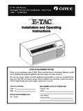
6 Minimum above the surface of the flat roof. Careshouldbetakentoensurefreedrainageofc ondensatefrom defrost cycles. This will prevent ice accumulation. Theheat pump should be located away from walkways to preventpossible icing from defrost condensate. Avoid placing the heat pump near areas such as sleepingquarters or study rooms. Normal operating sound levels maybe objectionable if the heat pump is placed near certainrooms. A shift in sound type does occur during the defrostmode. The defrost mode generally lasts no longer than Clearances To r c h in. Nut driver1. Outdoor rated disconnect switch2. NEC class 1 wiring3. NEC class 2 wiring4. House thermostat5. Seal openings48" OverheadClearance(DischargeAir)ToPowerSu pplyToIndoorUnitToIndoorCoil24" ServiceAccess Clearance12" Clearance (Inlet Air)12" Clearance BetweenUnit and Building12" Clearance(Inlet Air)12 3453 Electrical RequirementsNOTE:All wiring must be suitable for outdoor use.
7 Use copperconductors only. All field wiring must be done in accordance with NationalElectrical Code requirements, applicable requirements of UL,or local codes, where applicable. Electrical wiring, disconnect means and over currentprotection are to be supplied by the installer. Refer to therating plate for the maximum over current protection,minimum circuit ampacity, and operating voltage. See ShipmentThis heat pump is shipped in one package, completelyassembled and wired. The thermostat is shipped in a separatecarton when the heat pump rating plate to confirm specificationsare as receipt of equipment, carefully inspect it for possibleshipping damage. Take special care to examine the unitinside the carton if the carton is damage is found, it should be noted on the carrier s freight claims should be filed with the carrier of shortages should be filed with the seller within 5 :If any damages are discovered and reported to the carrier,do not install the unit because your claim may be Refrigerant LinesRefrigerant lines must be connected by a licensed, EPA certifiedrefrigerant technician in accordance with established : Connecting refrigerant lines must be clean, dehydrated,refrigerant-grade copper lines.
8 heat pumps should beinstalled only with specified line sizes for approved systemcombinations with elevation differences up to 20 ft and totallength of up to 50 ft. See the Suction Line Sizes and LiquidLine Sizes charts. Use care with the refrigerant lines during the installationprocess. Sharp bends or possible kinking in the lines willcause a reduction in performance. Do not remove the caps from the lines or system connectionpoints until connections are ready to be the suction and liquid lines from the fittings on theindoor coil to the fittings on the heat pump. Run the lines inas direct a path as possible avoiding unnecessary turns that the suction line is insulated over the entireexposed length and that both suction and liquid lines are notin direct contact with floors, walls, duct work, floor joists, orother valve the service valves with a wet Shock HazardElectrically ground heat ground wire to green pigtail copper wire for supply wire gauge is shown in the chart to follow these INSTRUCTIONS can result indeath or electrical Plate AmpacityLess than 1516-2021-30 AWG141210831-50 Excessive Weight HazardUse two or more people to move and installcondensing unit/ heat to do so can result in back or other the suction and liquid lines, using a brazingcompound.
9 Braze with an alloy of silver or copper andphosphorus with a melting point above 1,100 :Do not use soft sure indoor coil has been put in place according to theInstallation INSTRUCTIONS and is connected to the valve the lines and indoor coil with dry nitrogen not toexceed 20 test the refrigerant lines and indoor the indoor coil and lines to a minimum of 500microns to remove contamination and moisture, thendisconnect the vacuum the suction and liquid service valves the suction line with refrigerant line insulationmaterial of in. or more wall insulating material around refrigerant lines where theypenetrate the structure to protect the lines and to minimizevibration ChargeRefrigerant lines must be connected by a licensed, EPA certifiedrefrigerant technician in accordance with established : Refrigerant charge adjustment will be required for line setlengths greater than 20 ft.
10 And for non system matchedevaporator coils. The heat pump is factory charged with the proper refrigerantcharge amount for a matching evaporator and 20 ft ofrefrigerant line. Refer to the heat pump rating plate for theexact amount of this factory charge. Adjustment of the refrigerant charge will be necessary basedon the system combination and line length. To adjust therefrigerant size for increased line lengths and the followingamount of line set lengths greater than 20 refrigerant by weighing in oz. per foot of liquid refrigerant by weighing in oz. per foot of liquid line. If necessary, adjust the refrigerant charge for compatibilitywith the evaporator coil. In heat pump systems, horizontal suction lines should beslightly sloped toward the heat pump.