Transcription of High-performance Condenser Tube Cleaning …
1 High-performance Condenser Tube Cleaning system Featuring Advanced Ball Collecting Technology 116 High-performance Condenser Tube Cleaning SystemFeaturing Advanced Ball Collecting TechnologyOVERVIEW: Power companies are faced with an increasingly harshenvironment due to rapid deregulation and liberalization coupled andenvironmentally-friendly power generation, so maintaining the performanceof Condenser tubes that have such an enormous impact on the efficiency ofpower generation is emerging as a major issue. Since many of Japan s powerplants use sea water for cooling, it is critically important to maintaincondenser tubes used to cool large volumes of sea water in top performanceby preventing marine life in the water from getting into and clinging in thetubes and keeping the tubes clean.
2 These essential tasks are done by thecondenser tube Cleaning system . Pursuing R&D (research and development)based largely on the suggestions and guidance of various power companies,Hitachi has developed a High-performance tube Cleaning system with thehighest rated ball collecting ratio and installed the new system at ElectricPower Development Co., Ltd. s Isogo Thermal Power Station, Unit No. 1and Tohoku Electric Power Co., Inc. s Higashidori Nuclear Power Station,Unit No. 1. Based on accumulated knowledge and expertise in this area, wehave now developed the world s largest-class practical ball strainer andrecently finished installing the new system at Hokuriku Electric PowerCompany s Shika Nuclear Power Station, Unit No.
3 SuzukiKenchu Seki, Dr. k e o Ta k e iINTRODUCTIONCONDENSERS consist of many tubes for cooling andcondensing the exhaust steam from steam turbines. Acondenser tube Cleaning system (hereafter simply tubecleaning system ) is a closed recirculating loop in whichsponge Cleaning balls (hereafter Cleaning balls) areinjected into the Condenser cooling water. The cleaningballs pass through the tubes and polish and clean theinner tube surface. The Cleaning balls are then collectedby ball strainer that is located downstream from thecondenser tubes and re-injected by a ball recirculatingpump through ball injection nozzle installed on thecondenser cooling water inlet pipes.
4 Especiallyconsidering the growing importance and awareness ofenvironmental protection, it is essential to prevent thecleaning balls from getting out of the closed loopsystem and increase the Cleaning ball collecting ratioas high as possible. These concerns led Hitachi toconceive a tube Cleaning system that is easy to operateon a continuous basis without any of the Cleaning ballsescaping from the system by implementing a new typeof ball strainer that works with grids that arecontinuously closed and a ball-shell separator (see ). Having had excellent results with this approach oninstallations, we are now supplying the system onlarger capacity condensers .
5 This paper provides adescriptive overview of the tube Cleaning system andits OF EQUIPMENTC ondenser SpecificationsTube Cleaning systems are specifically engineeredto polish and clean Condenser tubes . Condenser tubesvary depending on the capacity of the power plant,but tubes to accommodate the largest class nuclearpower plant have a cooling surface of 102,000 m2 anda total tube length ( length number of tubes ) ofover 1,100 km (see Table 1).Tube Cleaning SystemThe tube Cleaning system basically consists ofcleaning balls that are slightly larger in diameter thanthe Condenser tubes . The balls are suspended and passthrough the cooling water to clean and polish the innerHitachi Review Vol.
6 54 (2005), No. 3 117objective is to achieve a Cleaning ball collecting ratioafter a Cleaning operation of 100%. Fig. 2 shows theconfiguration of a typical Cleaning tube system . Onecan see in the figure that the main components of thesystem are:(1) a ball injection nozzle for injecting balls into thecooling water at the Condenser inlet,(2) a ball strainer for collecting the Cleaning balls fromsurface of the tubes . Typically this is done once ortwice a day, and the length of the Cleaning ballrecirculating loop is four to five times the effectivelength of the Condenser tubes . Assuming that thecleaning balls pass through the Condenser tubes aboutfive times in one operation, they travel a total distanceof over 22,000 km in a single , the number of Cleaning balls is about10% of the number of Condenser tubes , and ourFig.
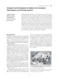
7 1 High-performance Ball Strainer and Large-capacity Ball Strainer.(a) Ball strainer with flapper for Tohoku Electric Power Co., Inc. s Higashidori Nuclear Power Station, UnitNo. 1, and (b) large-capacity ball strainer for Hokuriku Electric Power Company s Shika Nuclear PowerStation, Unit No. 2. Hitachi is unique in being the only domestic Japanese company that manufactures its owncondenser tube Cleaning systems, many of which are up and running at thermal and nuclear power plants inJapan and around the world.(a)Ball strainer with flapping screen(shell diameter: 3,500 mm)(b)Large-capacity ball strainer(shell diameter: 4,400 mm)TABLE 1. Main Specifications of Condenser for 1,350-MWCapacity Nuclear Power PlantLarge-capacity condensers with cooling area of 102,000 m2 andtotal tube length (length number of tubes ) of 1,100 2 Basic Structure of Tube Cleaning consists of a ball strainer, ball recirculating pump, ballcollector, ball injection nozzle, tubing, and surfaceTubeDiameterThicknessEffective lengthNo.
8 Of tubes3-shell surface type102,000 / mm17,790 mm63,864 Specification (per 3 shells)ItemCondenser cooling water systemCondenserBall injection nozzleBall strainerCirculatingwater pumpBall recirculating pumpBall recirculation lineBall collectorHigh- performance Condenser Tube Cleaning system Featuring Advanced Ball Collecting Technology 118the cooling water flow at the Condenser outlet,(3) a ball recirculating pump that delivers the ballscollected by the ball strainer back to the front of thecondenser tubes , and(4) a ball collector that stores and releases the cleaningballs into the Condenser FUNCTIONS ANDFEATURESBall StrainerThe ball strainer installed in the cooling waterreturn pipe downstream from the Condenser is the mostimportant component of the system , for it captures theballs after Cleaning and returns them to the condenserinlet pipes via the ball recirculation line.
9 The strainersection includes two grids forming a V-shaped ridgethat are kept closed (in capture mode) while thecleaning system is in operation. The balls are collectedin the grid valley, then are directed to the ballrecirculation line without restricting the cooling waterflow. Because the standard operating time is 1-2 hoursand balls are not recirculated outside of the operatingtime, the grid is opened to prevent increasing pressuredrop due to accumulated marine life at the ball the other hand, the balls travel a considerablerecirculation distance, as we observed earlier. If ballsstagnate en route along the Condenser cooling waterline, then they might be late in arriving, thus makingit likely that the balls will not all be collected by theball strainer within the typical operation time address this contingency, we conceived a ballstrainer with flapping screen that prevents any loss inthe ball collecting ratio and prevents balls fromescaping the system (see Fig.)
10 3).In order to collect the late-arriving balls mentionedin the previous paragraph, the ball strainer grids mustbe kept in a closed (capture mode) state. However, if aconventional ball strainer is operated in an alwaysclosed (capture mode) state, this causes two majorproblems:(1) If the ball strainer is operated in a closed (capturemode) state for a prolonged period, marine life anddebris accumulate on the surface of the grids, and thisis what causes the Cleaning balls to stagnate or remainuncollected.(2) Grid pressure loss increases as a result of incomingdebris accumulation, thus causing the grids to open atunpredictable intervals regardless of the operating stateof the tube Cleaning address these issues, we developed the ballstrainer with rotating flapping screen mounted on topof conventional V-shaped grids.