Transcription of High-speed Serial Bus Repeater Primer - Intel
1 High-speed Serial Bus Repeater Primer Re-driver and Re-timer Micro-architecture, Properties, and Usage Revision , Oct. 2015. By Samie B. Samaan, Dan Froelich, and Samuel Johnson, Intel Corporation 1. Introduction Target Audience This Primer aims to inform High-speed Serial bus Signal Integrity engineers and system designers on the characteristics of SerDes repeaters (re-drivers and re-timers), in order to enable proper and effective use of those devices. It also provides useful background and insights for hardware validation and debugging practitioners. Motivation and Scope Multi-gigahertz Serial links, with progressively increasing bitrates, suffer from signal distortion (Inter- symbol Interference, or ISI) due to PCB and package copper and dielectric losses. Other distortions also occur due to impedance discontinuities in the channels, such as vias, connectors, and packages. While a Serializer-Deserializer (SerDes) receiver (Rx for short) is designed to compensate for most of these distortions, and create an internal eye open enough for reliable sampling, bit rates are rising faster than Rx, PCB, or package high Density Interconnect (HDI) technologies can keep up with.
2 The result is that total channel reach is decreasing. Using expensive PCB materials to reduce loss will be reaching its dielectric limits soon, and adds significant cost. Next generation buses, such as PCI Express (PCIe) (16. Gb/s) and (10 Gb/s), which aim to double bit rates, will support shorter channel lengths (with similar high volume PCB materials) than their existing 8 Gb/s and 5 Gb/s predecessors, respectively. For the above reasons, and also various OEMs' desires for differentiation through larger/modular systems, entailing longer channels, there seems to be a rising need for active devices or Repeaters-- which restore the signals mid-flight, thus extending channel reach. This paper describes the two main classes of SerDes repeaters: The analog Re-drivers , and the mixed-signal (analog/digital) Re-timers . (both protocol-aware, and protocol-un-aware re-timers). This work describes the internal micro-architecture, properties, applications, and limitations of both types of SerDes repeaters.
3 It explains the subtle reasons why the presence of a re-driver in certain busses which require adaptive transmitter (Tx) Linear Equalization (TxEQ), such as PCIe , and 10G-KR, causes such links to be non-openly interoperable. It also addresses the special case of so-called Closed . Systems which do not require open interoperability (Section ). Furthermore, this document describes the functionality of PCIe and 10G-KR re-timers, in detail. 1. Signal Distortion in High-speed Copper Links Present multi-Gigahertz Serial busses carry bit streams ranging in their rates from around 1 Gb/s and up to (or exceeding) 32 Gb/s. The fundamental (Nyquist) or clock frequency of such patterns is half the bit rate. PCBs, packages, cables, and connectors make up the majority of copper-based Serial links, due to their cost effectiveness. Optical links are also used at high data rates and long reach, but they have different distortion mechanisms, and are not addressed directly here.
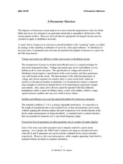
4 Copper (or metal) suffers from a resistance which increases with the square root of frequency, due to skin effect [1]. In addition, PCBs have losses in the dielectrics (resin and glass) used to make them [1]. The dielectric loss increases approximately linearly with frequency. Hence, depending on the dielectric loss constant (Dissipation Factor (Dk), tan( )), a PCB's trace loss ranges from having square root to linear dependence on frequency. For present day FR4 PCBs (whose Dk might range from to ) , the loss is dominated by the square root function at low frequencies, then becomes dominated by the linear dielectric loss at higher frequencies, as seen in Figure 1. Increasing attenuation with frequency causes signal distortion, and such distortion is worse for longer lines. When higher frequency components are attenuated, the bits (Unit Intervals, or UIs) begin to lose their sharpness, their tails extend beyond any single symbol (or bit), and start spilling over (interfering).
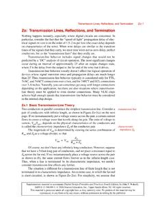
5 With subsequent symbols, hence the term Inter-symbol Interference (ISI). 0. -5. Gain, dB(Sdd21). -10. -15. -20. 0 2 4 6 8. Frequency, GHz Figure 1 Measured differential Insertion Loss (Gain to be precise) of a terminated PCB strip- line trace, showing an initial square-root-like dependence on frequency up to ~ GHz (skin-loss-dominated), then a linear dependence (dielectric-dominated). In addition to attenuation, there are also internal reflections in a channel, due to impedance discontinuities, causing further signal distortion. The impedance discontinuities in the channel are caused by inter-layer via transitions, connectors, decoupling capacitor parasitics, packages, imperfect terminations, etc. The insertion loss of such channels ( Figure 2) is usually more complex than that of a simple transmission line . It is noteworthy that a significant fraction of the smooth (frequency-dependent) distortion due to channel loss could be compensated for by using simple equalization circuits in the transmitter or the 2.
6 Receiver, whereas distortion caused by reflections is usually compensated by the more complex Decision Feedback Equalization (DFE) technique [2]. 0. -5. Gain, dB(Sdd21) -10. -15. -20. 0 2 4 6 8. Frequency, GHz Figure 2 Measured differential Insertion Loss (Gain to be precise), of a practical well-terminated channel employing 2 connectors, vias, and PCB traces. Introductory Description of Linear and Non-linear Systems In order to understand two main sub-types of repeaters called re-drivers, this section provides an initial brief definition of linear and non-linear systems (or circuits). More will be given on this topic in section A Linear System: Is one where the amplitude of the output response is directly proportional to the amplitude of the input, irrespective of the shape of the output. The output and input do not have to have the same shape for a system to be linear (since shape is controlled separately by the transfer function of the system, H(s)).
7 See section for more details. A Non-linear System: Is one where the amplitude of the output is not directly proportional to the input. The relationship between input and output amplitudes could be anything other than a straight line . In extreme cases, it could be a step function, as the input amplitude rises, there is no output initially, but then suddenly an output appears, and remains at about the same amplitude even if the input amplitude keeps rising. Such a system is a Sharply-limiting non-linear system. In more moderate cases the output amplitude reaches saturation gradually. See section for more details. 2. Repeater Types Fundamentally, High-speed Serial repeaters are of two types: Re-drivers, and Re-timers. Re-driver This is usually a high -gain-bandwidth amplifier, employing input Continuous Time Linear Equalization (CTLE, [3]) and sometimes also output Transmitter Linear Equalization (TxEQ [3] [4]). The amplifier could be either linear or non-linear (limiting).
8 These devices have no clock, and are pure analog devices, except for the presence sometimes of a sideband low-frequency bus to program their analog settings. Limited 3. programming is usually also achievable by using strap pins. Re-drivers do not store data digitally, nor could they be protocol-aware. They just compensate for ISI, cause a delay of the signal by a few 100s of pico-seconds, and usually add some jitter. Re-drivers are not specified directly in most Hi- speed Serial bus standard specifications. If not addressed explicitly in a bus's specification, then in general, using re-drivers renders a link non- compliant, strictly speaking. Their use in such busses as USB3 and SATA3 is Extra-spec (which might be surprising to some, but can be gleaned from careful reading of those specifications), but appears to be tolerated practically. More details on these devices' usage and subtleties will be given in later sections. Re-timer A device which has a Clock & Data Recovery circuit (CDR [5] [6]), which is the main component of a SerDes Physical Layer (PHY).
9 A re-timer has a Phase Locked Loop (PLL [7]), may require an input Reference clock, and is a mixed-signal analog/digital device. It converts an incoming analog bit stream into purely digital bits that are stored (or staged) internally. The internal digital data has no analog information left in it from the incoming original bit stream. A re-timer re-transmits data anew, with new equalization, and new jitter content, unrelated analog-wise to the input bit stream. Thus, a re-timer breaks a link into two distinct sub-links, which are completely independent from each other, from a Signal Integrity (analog amplitude and timing) perspective. Some Re-timers also provide debug capabilities, such as eye margining, link status, and link health indicators. In addition, sophisticated re- timers, which are protocol-aware, comprise digital logic to manage link initialization, training, data encoding and decoding, and clock domain frequency differences.
10 Re-timers are more complex than re-drivers, larger in die and package size, are more expensive, and, as of this writing, are offered by fewer vendors than re-drivers. Re-timers are, in turn, of two types: Simple Bit Re-timers and Intelligent Re-timers . Bit re-timers are usually Protocol unaware, &. usually TxEQ Training-incapable, while intelligent Re-timers are Protocol-aware, and TxEQ Training- capable. Section 13 provides more details on re-timers. 3. Re-drivers Re-driver Micro-architecture This section discusses the generic internal micro-architecture of a re-driver. Any vendor's re-driver might have a different specific design, but they all share these general features. Figure 3 shows the internal components of a differential re-driver (See section ). Re-drivers usually come as an identical pair (or set of pairs) in one package as shown in Figure 4, in order to accommodate the sending and receiving signal directions of one or more lanes.