Transcription of High Speed SPI Slave Implementation in FPGA using Verilog …
1 International Journal of Advanced Research in Computer Engineering & Technology (IJARCET). Volume 4, Issue 12, December 2015. High Speed SPI Slave Implementation in FPGA. using Verilog HDL. Mr. Akshay K. Shah protocol is called synchronous because operation is Abstract SPI (Serial Peripheral Interface) is a controlled by this clock only. synchronous serial communication interface for short distance SPISTE (CS) Chip Select. This signal is used by a communication. It is also called a four-wire serial bus.
2 SPI. master to select a Slave from the number of slaves Devices communicate in full duplex mode in Master- Slave architecture with a single master. It's operation is relatively connected on the bus. very simple and operating Speed is very high. The designed SPI Data Wires: Slave in FPGA will communicate with a DSP at relatively high MISO/SOMI - Master In Slave Out. Data input from Speed . Slave to master. MOSI/SIMO Master Out Slave In. Data output Index Terms Serial Peripheral Interface (SPI), Field from master to Slave .
3 Programmable Gate Array (FPGA), Digital Signal Processor (DSP). Printed Circuit Board(PCB), USB (Universal Serial Bus), I. INTRODUCTION. We generally prefer serial communication over parallel communication, as serial communication provides number of advantages like improved noise integrity, less number of pin counts and also high Speed . We use different protocols for both long and short distance communication. Long Distance: Ethernet, Serial-ATA (SATA), USB, etc. Short Distance: I2C, SPI, etc. There are number of ICs of memories ( FRAM, EEPROM, etc.)
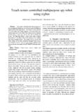
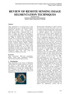
4 Available in the market which, we can operate as a Slave . We can readily use these ICs Data Transfer in SPI Interface by implementing a SPI master Implementation in either microcontroller/FPGA/DSP. There are four operating modes available in SPI standard But there are certain cases where we do not require protocol which can be determined by the polarity of clock that much memory in terms of number of registers polarity (CPOL) and clock phase (CPHA). Both master and as well as we want to manipulate that received data Slave have to run in the same mode in order to achieve the for other purposes in different application.
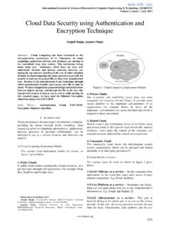
5 Proper communication between them. In that cases we can build our user defined memory in FPGA and we can build a SPI Slave module SPI MODE CPOL CPHA. inside FPGA that can interface serially with any SPI. 0 0 0. Master at very high Speed in full duplex mode. 1 0 1. II. SPI PROTOCOL 2 1 0. 3 1 1. SPI is a synchronous 4-wire protocol which uses 4-wires for establishing a full duplex communication between master CPOL = 0: and Slave . As stated above, there can be only one master and CPHA = 0 transmits data on rising edge and receives on any number of slaves can be connected.
6 Falling edge of the SCLK signal (Rising edge without Four Wire- Two control wires and two data wires: delay). Control Wires: CPHA = 1 transmits data one half-cycle ahead of rising SPICLK Clock Signal generated by a master. This edge and receives on rising edge of the SCLK signal (Rising edge with delay). 4365. ISSN: 2278 1323 All Rights Reserved 2015 IJARCET. International Journal of Advanced Research in Computer Engineering & Technology (IJARCET). Volume 4, Issue 12, December 2015. SPI Slave Module Implementation Block Diagram &.
7 Different Modes of SPI Interface Application Example CPOL = 1: Command frame [16 bits] consists of synchronization bits CPHA = 0 transmits data on falling edge and receives on (To check and confirm the clock & data synchronization), rising edge of the SCLK signal (Falling edge without Read &/ Write command & 5 address bits while other bits are delay). reserved for future use. CPHA = 1 transmits data one half-cycle ahead of falling edge and receives on falling edge of the SCLK signal (Falling edge with delay).
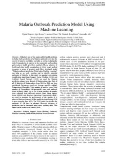
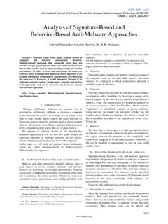
8 III. PROPOSED Implementation . SPI Slave MODE-0 (Rising edge without delay). configuration is implemented in FPGA. DSP acts as a master and Slave module is implemented inside FPGA. FPGA global clock is driven by an external clock source. Block Diagram A memory of 32 registers each of 16- bits wide is created inside FPGA which can be addressed with the help of 5. address lines. These address bits can be decoded from the incoming command bits. As shown in , there are different control logics inside Slave module of FPGA, that can interpret the incoming frame from master and take decision according to the command present inside the frame.
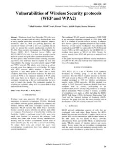
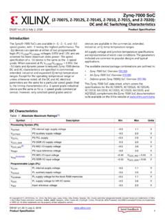
9 Data written inside memory is utilized for number of applications as shown in The frame structure is as shown in the Table-1. 31---16 15---0. Command Frame Data bits Decode Logic Flow Chart Table-1 32-Bit Frame Structure Command frame coming from master decides the communication flow as under: [ ]. 4366. ISSN: 2278 1323 All Rights Reserved 2015 IJARCET. International Journal of Advanced Research in Computer Engineering & Technology (IJARCET). Volume 4, Issue 12, December 2015. If WR (write) command is given from the master then Slave waits for the next 16-bits of data and after receiving all 32-bits, Slave latched this data and writes data into the register of specified address.
10 If RD (Read) command is given from master then, Slave does not wait for the next 16-data bits. After receiving 16-bits of command, it loads the serial register with the data from register of specified address, and from the 17th clock Slave transmits these data to the master on the MISO pin. If RD&WR (Both in a single command) are given then Slave combines above two operations and operates in full duplex mode. After receiving first 16-bits it transmits the contents from specified address to master from 17th clock to 32nd clock.