Transcription of Holden Engine Troubleshooter Reference Manual - Snap-on
1 Holden EngineTroubleshooter Reference ManualUse in conjunction with the applicable Scanner User s Reference Manual and Diagnostic Safety Software February 2009 Safety Warnings and CautionsRefer to Diagnostic Safety 2009 BEFORE OPERATING THIS UNIT, PLEASE READ THIS Manual AND ANY APPLICABLE SCANNER AND SAFETY effort has been made to ensure that the information in this Manual and software is accurate. The right is reserved to change any part at any time without prior responsibility is taken for any technical or printing errors that might occur in this Manual or 2009 Snap-on Technologies Engine Troubleshooter Reference ManualHoldenIntroduction About the Fast-Track Troubleshooter System.
2 2 Using Troubleshooter Effectively ..3 Troubleshooting Trouble Codes ..3 General Circuit Testing Information ..4 Holden Reference Bulletins Index ..7 PAGE 1 CAUTION1. Always read Scanner and Safety Manuals Ensure correct ID on Scanner and connections correct for Always check for fault codes first checking KOEO, KOER and memory codes in Self 2 About the Fast-Track Troubleshooter SystemSnap-on s Fast-Track Troubleshooter is a unique time saving diagnosis tool which compliments the Snap-on Scanner. They are used in unison to diagnose and repair EFI related problems.
3 The Troubleshooter incorporates known faults & repair tips, component testing & technical assistance to reduce the down time of diagnosis, therfore saving you time and money. This product is researched and made in Australia for Australian Vehicles. Information is researched from throughout Australia from a large network of technical sources with vast knowledge of Reference Manual supplied in this kit contains additional information to support many Troubleshooter tips when special instructions, specifications, pinouts and wiring diagrams are needed as indicated by the : The Fast-Track Troubleshooter system contains information on the most common code problems and driveability complaints on the above vehicles.
4 It does not, however, contain information for every possible code and every possible problem that could occur in all 3 Using Troubleshooter EffectivelyThe checks in each Troubleshooter tip begin with the most likely cause of a problem or with the tests that should be made first. The checks then progress through other possible causes and tests. All checks in a tip are common causes of a problem or important basic tests, and the most important are listed first. For the most effective use of the Troubleshooter tips, follow the checks in the order in which they are checks in the Troubleshooter tips with refer you to references in this Troubleshooter Manual .
5 Consult the references as directed by the tips on the Troubleshooter . Trying to use the references by themselves may cause you to miss important information or to perform some test or adjustment out of procedures in the Troubleshooter the vehicle s ignition switch will be required to be switched OFF (eg: for disconnecting connectors etc). This will cause the communication between the Scanner and vehicle to drop out. Sometimes the Scanner will read No Communication or drop completely out and sometimes it will still show Troubleshooter information. Note if Troubleshooter information remains on screen, any data parameters shown will be those prior to switching ignition off and will not change due to no ignition power.
6 Ensure ignition is on and vehicle s PCM is communicating whenever checking any data with the basicsThe Fast-Track Troubleshooter tips deal with automatic transmission electronic systems and controls. Many tips also contain directions to check fuel, ignition, and other electrical components. As a general rule, basic fuel system, ignition, and electrical tests, as well as a thorough inspection, should be made before performing pinpoint tests on electronic ensure that the following systems and components are in proper operating condition: Battery condition Electrical connectors and wiring harnesses Vacuum lines and connectors General Engine mechanical condition Brakes and differential assembliesTroubleshooting Trouble CodesTrouble codes should be diagnosed and serviced in a basic order: First, hard codes for currently present problems.
7 Followed by soft, or memory, codes for intermittent vehicles transmit codes in numerical order from the lowest to the highest. This is basically the order in which they should be serviced, with current codes being diagnosed before history codes. Code 51 and some other 50-series codes are the exceptions to this general rule. Code 51 for many GM vehicles indicates a PROM fault and should be serviced before other codes. Other 50-series codes that relate to PROM or PCM problems also should be diagnosed before other distinguish between a current (hard) code and an intermittent (soft) code on most GM vehicles, clear the codes from PCM memory.
8 Then drive the vehicle and watch for the code to reappear. If it reappears immediately or soon, the code usually indicates a hard fault. If the code does not reappear quickly, it was probably a soft code, indicating an intermittent problem. Some late-model GM cars also have a code history section which shows up to the last four fault codes logged with a history of when they occurred. Refer to Reading, using and clearing codes in the Troubleshooter Technical Assistance General Information 4 General ReferenceGeneral circuit testing (voltage drop testing)In most cases, measuring the voltage at various points in a circuit will tell you more about the circuit integrity than measuring the circuit resistance (ohms).
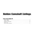
9 A good circuit consists of the supply voltage, a load, and a ground. The load should be activated when current passes through it. A load is any electrical component, such as a lamp, a motor, a solenoid, or a relay. Most electrical circuits also include a fuse on the supply side to protect the load in the event of a short or power surge. Typically, mechanically-switched circuits, such as headlamps and wiper motors, have a switch on the supply side of the load. Electronically-switched circuits such as a TCC solenoid or an EGR solenoid, are usually ground-side switched.
10 Remember, many switches actually energize a relay which, in turn, activates a determine if a circuit is good, check the supply voltage to the load, and check the ground. Figure 1 shows you how to test the supply voltage. Connect the positive (+) DVOM lead to pin A of the load, and the negative (-) DVOM lead to chassis ground. With the switch closed, the DVOM indicates a good supply voltage ( volts) at pin A of the load. This typically indicates that the supply side of the circuit is good. It also indicates that the fuse is not blown. If the fuse was blown, the DVOM would indicate zero volts on the supply side of the 2 on the next page shows you how to test the ground side of the circuit.