Transcription of Hole Alignment Tolerance Stacking Issues
1 Technical Document Series Hole Alignment Tolerance Stacking Issues M&CT -TECH-99-025 October 1999 Mathematics and Computing Technology Phantom Works Phantom Works, Mathematics & Computing Technology A Division of The Boeing Company BOEING THIS DOCUMENT IS: Controlled by Mathematics and Engineering Analysis, G-6400 Prepared under D Contract DIR&D DCD/OH D Prepared on Sun Filed under Document No. M&CT-TECH-99-02S Title Hole Alignment Tolerance Stacking Issues Original Release Date October 1999 @ The information contained herein is NOT BOEING PROPRIETARY or BOEING LIMITED o Boeing Limited o Boeing Proprietary Prepared by: Fritz Scholz Approved by: Roberto E. Altschul i Hole Alignment Tolerance Stacking Issues Fritz Scholz M&CT-TECH-99-025 October 1999 Copyright 1999 The Boeing Company Phantom Works Mathematics and Computing Technology Box 3707, MIS 7L-21 Seattle, WA 98124-2207 Hole Alignment Tolerance Stacking IssuesFr i t z S ch o l z Mathematics and Computing TechnologyBoeing Phantom WorksFebruary 24, 1999 AbstractEach of two parts hasKcoordination holes with the intent that each hole on onepart is paired and to be pinned with a corresponding hole on the other part.
2 Whilethe nominal hole centers for each hole pair are identical, the actual hole centers willdeviate from their nominal values in some random fashion re ecting the inherent holecentering accuracy of the drilling process. It is then of some interest to examine themaximal hole center discrepancy amongKsuch hole pairs and to understand how thisdiscrepancy grows withK. We give a plausible and very simple model for assessingthis maximal discrepancy statistically and show that the growth of this discrepancy isslow, namely on the order ofplog(K). Although this model formulation assumes theunrealistic true position part Alignment on allKnominal centers, it is still useful inthat it provides a conservative assessment compared to what might be possible under\best" Alignment .
3 Furthermore, its results relate essentially linearly to the common,practical Alignment procedure using primary and secondary hole pairs. The statisticaltreatment of hole center variation is compared to the worst case treatment for bothalignment procedures. While the gain of the statistical over worst case treatment issmall under true positioning it is substantial under primary/secondary hole for minimal clearance and maximal clean-out diameters are derived,assuming no or negligible hole and pin diameter variations. These results can beextended usefully to the situation when triplets of holes, one hole each on one of threeparts, need to be pinned. The above results are derived assuming equal hole centeringvariability from hole to hole.
4 This is extended to hole centering variability that growslinearly with the distances of the nominal hole centers from some reference datum. Afurther extension deals with matching two parts where each part is built up fromksubparts withnholes each. The misalignments of the subparts relative to each otheradd dependency complications when trying to assess the maximum mismatch betweentheK=knholes on each assembly half. Box 3707, MC 7L-22, Seattle WA 98124-2207,e-mail: Problem Description and Overview12 Clearance & Clean-Out under True Position Clearance and Clean-Out Distributions forKHoles .. Clean-OutToleranceStackCriterionandFallo utRate .. 173 Alignment Using Primary and Secondary Hole ClearanceToleranceStackandFalloutRate.
5 CleanoutToleranceStackCriterionandFallou tRate .. 344 Comparison with Worst Case Comparison under True Position Comparison under Primary/Secondary Hole Alignment .. 395 Three Matched ClearanceforThreeMatchedHoles, Clean-OutforThreeMatchedHoles,TruePositi onAlignment .. Clean-OutUnderPrimary/SecondaryHoleTripl etAlignment .. 606 Hole Centering Variation Increasing with Datum Distance677 Mating Coordination Holes on Assembled Parts758 References899 Appendix AExtreme Value Approximation9010 Appendix BGeometry of Primary/Secondary Hole Pair Alignment9111 Appendix CClearance and Cleanout for Three Overlapping Holes9812 Appendix DWorst Case for Primary/Secondary Hole Pair Alignment1041 Problem Description and OverviewWe consider various aspects of the coordination hole Tolerance Stacking problem.
6 They arisewhen trying to mate two parts, such as stringers to skins, skins to skins, and panels toframes, etc., by placing (temporary) fasteners through matching hole pairs or hole there will beKsuch hole pairs or triplets, whereK 2andKmay be as large as60 or such fasteners are temporary, their function is to act as clamping devices thathold the parts in position while intermediate holes are match-drilled and riveted. Since suchriveting xes the position of the parts relative to each other, these coordination holes alsoserve the much more important role of de ning the geometry or nal position of the two partsrelative to each other. The temporary fasteners are removed after riveting the intermediateholes.
7 The coordination holes are then cleaned out, , match-drilled with larger, full-sizedholes and ning the relative geometry of parts by coordination holes di ers from previous prac-tices of using massive tools for joining parts. There the tools carry the geometry informationwhich is transferred to the parts by holding them in place in the tools while match drillingand riveting them. This process results in variation in the geometry as de ned on the tooland in variation in xturing the parts on the tool. The variation in the geometry as de nedon the tool acts more like a bias, xed e ect, or mean shift which does not lend itself very wellto statistical variation cancellation. Such biases would repeat themselves time and again,unless there is some slow drift in the tool geometry, which represents another systematicvariation the coordination hole scenario was the original motivation for looking at thisproblem, the analysis methods proposed here have a wider scope.
8 Namely, they are relevantwhenever several particular feature point locations on one part need to be mated to corre-sponding feature point locations on another part. In the above motivating example thesefeature point locations would be the hole centers. Typically such feature point locations aresubject to variation which leads to mismatches when more than one pair of such featurepoint locations needs to be aligned. Assessing the maximal size of this mismatch (over allfeature point location pairs) from a statistical and worst case perspective is our main the scope of the methods presented here goes beyond pinning coordinationholes we will stay with that application image to avoid complete abstraction.
9 A crucial initialassumption underlying the analysis methods developed here is that during assemblythe partsare aligned by matching the nominal hole center positions for each hole pair. Since these1nominal hole center positions are also called thetrue positionsof these particular features,we refer to this part Alignment also astrue position Alignment . This particular alignmentis arti cial, because it is not at all clear how to accomplish it in practice. However, if it ispossible to pin the parts loosely and without interference under true position Alignment , itwill also be possible to pin the parts under some other nearby alignments as well. It is just amatter of nding such alignments through small motions of the parts relative to each all these alignments there certainly will be a best one, , with smallest maximumhole center discrepancy.
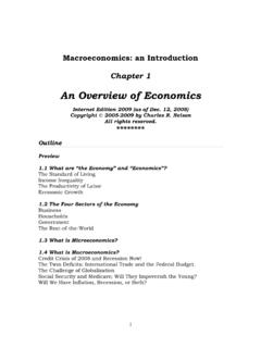
10 Considering the true position Alignment case is therefore in somesense a conservative assessment of the pinning problem. By \conservative" we mean thateven if it is established that the parts cannot be pinned under true position Alignment , suchpinning may still be possible under some other 1: Hole Clearance DiameterC clearance diameter Cnominal centerBeing able to put fasteners or pins through all the paired holes simultaneously is referredto as theclearance problem. Since the paired holes have actual hole centers that deviate fromtheir respective common nominal centers, these paired holes can be viewed as overlappingcircles which de ne a maximal inscribed circle, shown shaded in Figure 1.