Transcription of POWER 25 - SolarEdge
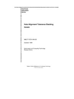
1 POWER Optimizer For North America P370 / P400 / P401 / P485 / P505 25 YEAR WARRANTY PV POWER optimization at the module-level Specifically designed to work with SolarEdge inverters Up to 25% more energy Superior efficiency ( ) Mitigates all types of module mismatch losses, from manufacturing tolerance to partial shading Flexible system design for maximum space utilization Fast installation with a single bolt Next generation maintenance with module- level monitoring Meets NEC requirements for arc fault protection (AFCI) and Photovoltaic Rapid Shutdown System (PVRSS) Module-level voltage shutdown for installer and firefighter safety POWER OPTIMIZER POWER Optimizer For North America P370 / P400 / P401 / P485 / P505 Optimizer model (typical module compatibility) P370 (for higher- POWER 60 and 72-cell modules) P400 (for 72 & 96- cell modules) P401 (for high POWER 60 and 72 cell modules) P485 (for high-voltage modules) P505 (for higher current modules) INPUT Rated Input DC POWER (1) 370 400 430 485 505 W Absolute Maximum Input Voltage (Voc at lowest temperature) 60 80 60 125(2) 83(2) Vdc MPPT Operating Range 8 - 60 8 - 80 8-60 - 105 - 83 Vdc Maximum Short Circuit Current (Isc)
2 11 11 14 Adc Maximum DC Input Current Maximum Efficiency % Weighted Efficiency % Overvoltage Category II OUTPUT DURING OPERATION ( POWER OPTIMIZER CONNECTED TO OPERATING SolarEdge INVERTER) Maximum Output Current 15 Adc Maximum Output Voltage 60 80 Vdc OUTPUT DURING STANDBY ( POWER OPTIMIZER DISCONNECTED FROM SolarEdge INVERTER OR SolarEdge INVERTER OFF) Safety Output Voltage per POWER Optimizer 1 Vdc STANDARD COMPLIANCE EMC FCC Part 15 Class B, IEC61000-6-2, IEC61000-6-3 Safety IEC62109-1 (class II safety), UL1741, NEC/PVRSS Material UL94 V-0 , UV Resistant RoHS Yes INSTALLATION SPECIFICATIONS Maximum Allowed System Voltage 1000 Vdc Compatible inverters All SolarEdge Single Phase and Three Phase inverters Dimensions (W x L x H) 129 x 153 x / x 6 x 129 x 153 x / x 6 x 129 x 153 x / x 6 x 129 x 159 x / x x 129 x 162 x 59 / x x mm / in Weight (including cables) 630 / 750 / 655 / 845 / 1064 / gr / lb Input Connector MC4(3) MC4(3) MC4(3) Input Wire Length / m / ft Output Wire Type / Connector Double Insulated / MC4 Output Wire Length / m / ft Operating Temperature Range (4)
3 -40 to +85 / -40 to +185 C / F Protection Rating IP68 / Type6B Relative Humidity 0 - 100 % (1) Rated POWER of the module at STC will not exceed the optimizer Rated Input DC POWER . Modules with up to +5% POWER tolerance are allowed (2) NEC 2017 requires max input voltage be not more than 80V (3) For other connector types please contact SolarEdge (4) Longer inputs wire lengths are available for use. For input wire length order P401-xxxLxxx (5) For ambient temperature above +85 C / +185 F POWER de-rating is applied. Refer to POWER Optimizers Temperature De-Rating Technical Note for more details: PV System Design Using a SolarEdge Inverter(6)(7) Single Phase HD-Wave Single phase Three Phase for 208V grid Three Phase for 277/480V grid Minimum String Length ( POWER Optimizers) P370, P400, P401 8 10 18 P485, P505 6 8 14 Maximum String Length ( POWER Optimizers) 25 25 50 Maximum POWER per String 5700(8) (6000 with SE7600-US - SE11400-US) 5250(8) 6000(9) 12750(10) W Parallel Strings of Different Lengths or Orientations Yes (6) For detailed string sizing information refer to.
4 (7) It is not allowed to mix P485/P505 with P370/P400/P401 in one string (8) A string with more than 30 optimizers does not meet NEC rapid shutdown requirements; safety voltage will be above the 30V requirement (9) For 208V grid: it is allowed to install up to 6,500W per string when the maximum POWER difference between each string is 1,000W (10)For 277/480V grid: it is allowed to install up to 15,000W per string when the maximum POWER difference between each string is 2,000W SolarEdge Technologies Ltd. All rights reserved. SolarEdge , the SolarEdge logo, OPTIMIZED BY SolarEdge are trademarks or registered trademarks of SolarEdge Technologies, Inc.
5 All other trademarks mentioned herein are trademarks of their respective owners. Date: February 10, 2022 DS-000044-NA. Subject to change without notice.