Transcription of Horizontal Wall Post Indicator - Viking Group Inc.
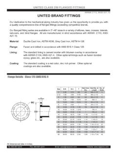
1 Worldwide Fire PostsHorizontal Wall post Indicator 641 SItem DescriptionMaterial Specification1 Eye Bolt Steel1/2 -UNC2 Nut Steel1/2 -UNC3 Washer Steel5/8 4 HandwheelCast IronASTM 126 IronASTM 126 Ring Steel# StemBronzeAWWA A 8 Nuts Plated Steel1/2 -UNC9 Bolt Plated Steel1/2 -UNC x 2 10 Bolt Plated Steel1/2 -UNC x 13/4 11 BodyCast IronASTM 126 NutBronzeAWWA A 13 Windows - FlatPlasticPlexiglass14 Screw Plated Steel1/4 x 3/4 Self Tap15 FerruleSteel16 Protective Steel PlateSteel17 Target Plates (Open/Shut)AluminiumCast18 Clamps - PlatedPlated Steel19 Nuts Plated Steel1/4 - 20 UNC20 Machine Screw Brass1/4 - 20 x 7/8 21*Pipe PlugMalleable Iron1/2 NPT22 Stem Steel1 Square23 Cotter PinBrass24 Crane CouplingCast IronASTM 126 (mm / inch)Weight (kg/lbs)A BC641S514 / / / / 91 Wall Type Indicator post - 641S Physical DataHorizontal Wall post Indicator - 641S Materials ListManufactured for Viking SupplyNet by Kennedy Valve, division of mcwane Inc.
2 Refer to Manufacturer s datasheet. Specifications subject to change without the datasheet of 2004-09-10 (Changed Top Section (11) t o Body in Materials List and Installation) Worldwide Fire PostsManufactured for Viking SupplyNet by Kennedy Valve, division of mcwane Inc. Refer to Manufacturer s datasheet. Specifications subject to change without Wall post Indicator 641 SInstallationNOTE: Ensure that the non-rising stem gate valve is in the fully open position before installing the Wall post Indicator . 1.) Make the wall through holeMake a clearance hole that is at least 120mm ( ) in diameter but not greater than 180mm ( ) in diameter through the mounting wall. The clearance hole must be on-center and concentric with the operating nut of the non-rising stem gate valve. NOTE: A DN100 / 4 ( Outside Diameter) length of pipe can be used to line the inside of the through hole. Pipe of this diameter will fit snugly into a machined mating hole on the flange side the Body (11) of the Wall post ) Drill the Mounting HolesDrill 4 equally spaced holes on a 267 mm ( ) bolt circle into the mounting wall using a (19mm) drill bit.
3 The bolt circle must be concentric and on center with the operating nut of the non-rising stem gate ) Mount the Wall post IndicatorBolt the flange of the Body (11) of the Wall post Indicator to the wall using 4 bolts. 4.) Remove the CoverWith the Body (11) flange of the Wall post Indicator securely bolted to the mounting wall, remove the Cover (5) by removing the two Bolts (8) and (9). Slide the Cover (5) off of the Wall post Indicator Body (11) .5.) Insert and measure the Stem RodWith the Cover (5) still separated from the Body (11), slide the Stem Rod (22), Cotter Pin (23) and Crane Coupling (24) assembly through the Wall post Indicator Body (11) and through the wall such that the Crane Coupling (24) fully engages with the operating nut of the non-rising stem gate valve. With the Crane Coupling (24) fully engaged on the operating nut of the non-rising stem gate valve, put a mark on the Stem Rod (22) that is between (32mm) below the top surface of the Body (11) but not more than 2 (50mm) above the top surface of the Body (11).
4 6.) Cut the Stem RodCut the stem rod at the mark made in Step 5. 7.) Adjust the Target PlatesAdjust the Open Target Plates (17) such that they are squarely centered in the Windows (13) when the non-rising stem valve is in the fully open position. Repeat this procedure with the Shut Target Plates (17) when the non-rising stem gate valve is fully closed. Adjustment is made is made by loosening Square Nuts (20) and Clamps (19).8.) Re-assemble the Wall post IndicatorInsert the Cover (5) back onto the Top Section (11) such that the ears on either side of the Target Nut (12) fit into the grooves on the inside edges of the Body (11). Tighten the two Nuts and Bolts (8)(9). Verify that the Open and Shut Target Plates (17) are in the proper position by fully opening and closing the non-rising stem gate valve using the Handwheel (4). Adjust as the bearing in the Body (11) at least once a year by adding several drops of oil in the hole located on the top of the Operating Nut (2).
5 2004-09-16 Updates the datasheet of 2004-09-10 (Changed Top Section (11) to Body in Materials List and Installation)

![Untitled-1 [pe.mcwane.com]](/cache/preview/0/6/a/a/7/a/e/3/thumb-06aa7ae3820fc1a116eff00b799cf8bf.jpg)