Transcription of How Mitsubishi’s Factory Boost Control System Works v1
1 COBB TUNINGT echnical DocumentationHow mitsubishi s Factory Boost Control System Works document is intended to assist you with the understanding of how turbo Boost pressure is controlled on an internally (or externally) wastegated turbocharger through the Factory Boost Control System . In order for the Boost pressure to be properly controlled by the stock Boost Control System , we must show you how to properly set-up or calibrate your internally or externally wastegated turbocharger. This document is broken down into four chapters; Hardware, Plumbing, Hardware Function, & Mechanical Calibration. Please read the following thoroughly before you attempt to tune your mitsubishi EVO with the AccessECUTM software. In the AccessECU StreetTUNERTM or ProTUNERTM software, Descriptions and Tuning Tips for most of the tables are provided and can be accessed by pressing the F1 key while that table is highlighted in the Table would like to go into further detail about the safeguards and advanced tuning features that are available through the AccessECU software.
2 The Boost Control System uses a closed-loop targeting System which does everything it can to make the Boost Control System consistent. By employing this closed-loop Boost Control System the electronic Control unit (ECU) can use its speed to bring down Boost in overboost situations and raise the wastegate duty cycles (WGDC) for underboost situations. The stock Boost Control System is much faster than any human analysis and input; we highly suggest you use it to your advantage. Once the stock Boost Control System is fully understood you will find it easy to tune on internally or externally wastegated 2006 Cobb Tuning, Inc. All rights ORDER FOR ANY AccessPORT CALIBRATIONS TO Control Boost PROPERLY WITH THE mitsubishi EVO, you must first remove the secondary restrictor pill located in the forward-most vacuum line connected to the wastegate solenoid valve.
3 In order to remove this secondary restrictor pill please follow the below instructions: Step 1a Step 1b1 Disconnect negative battery terminal and remove the fresh air inlet. Set all hardware aside where it cannot be kicked or Take forever and a day to remove the undercarriage aerodynamics tray. Take your time so that you do not break the majority of the fasteners. This piece is very critical in function, it allows the radiator to work more efficiently and it creates more downforce in the front of the vehicle so be sure to reinstall it with all of the proper Factory fasteners once you are finished. Step 3a Step 3b3 Disconnect the MAF plug from the sensor, and remove the stock airbox by unscrewing the two 10mm bolts that hold down the Factory 2006 Cobb Tuning, Inc. All rights 3cYou can leave the MAF sensor and air filter inside the fully assembled air box so those pieces can be removed as one assembly.
4 Set all hardware aside on the ground where it cannot be kicked or misplaced. Step 4a Step 4b4 Remove the 12mm bolt holding the lower aluminum portion of the IC piping to its upper brace. Remove the 12mm bolt holding the lower aluminum portion of the IC piping to its lower 2006 Cobb Tuning, Inc. All rights 4cLoosen three hose clamps; one from the uppermost intercooler coupler, one from the BOV return line, and one on the coupler that goes to the lower aluminum portion of the IC piping. This will allow you to completely remove a section of the IC piping so you have better access to the plumbing for your Factory Boost Control System . Step 6a Step 6b6 Remove the two 10mm bolts from the radiator fan Control box. Disconnect the small, black radiator fan connector but be sure to leave the large, grey connector plugged in to the Control box and just place the box to the 2006 Cobb Tuning, Inc.
5 All rights reserved. Step 7a Step 7bStep 7c7 Remove the two 10mm screws from the upper radiator shroud. Gently push the lower aluminum portion of the IC piping away from the shroud so the shroud/fan assembly can be easily pulled up and removed from the vehicle. Be careful to not allow anything to touch the delicate fins on the back of the radiator. If any radiator fins are bent in this process, please do what you can to gently bend them back in their original 2006 Cobb Tuning, Inc. All rights 8a8 Remove the vacuum line that is attached to the forward-most nipple on the wastegate solenoid valve. The secondary restrictor pill is located inside this vacuum line close to the end that is attached to the wastegate solenoid valve. This secondary restrictor pill must be removed from the Boost Control System in order for ANY AccessPORT calibration to properly Control Boost on the mitsubishi EVO.
6 The easiest way we have found to remove the secondary restrictor pill is to squirt some silicon spray into the end of the hose which contains the secondary restrictor pill. You can then squeeze out the pill with your fingers or use a pick to work it out of the hose. Another option is to completely replace this vacuum line with a new, similarly-sized silicon line that has no restrictor pill inside. Please install all items in the reverse order they were removed. Be very careful when setting the radiator shroud/fan assembly back into place, the fins on the radiator are very delicate and can bend very easily. If any fins are bent in the installation process, please do what you can to bend them back in their original must remove this secondary restrictor pill in order for any AccessPORT calibration to Control Boost properly on your mitsubishi 2006 Cobb Tuning, Inc.
7 All rights 1 HardwareTurbo - An exhaust driven air compressor which consists of four basic sections or components. The compressor section consists of the compressor housing and the compressor wheel. This section acts as the inlet or intake for the turbo, compressing the intake charge and generating relative pressure ( Boost ). Generally speaking the inlet is always in a vacuum, sucking air in and the outlet is pressurized with the intake charge. Next is the center section which contains the bearings, shaft, and the oil and anti-freeze passage ways; the compressor and turbine wheels are also attached to the shaft in this section. The third section is the turbine section which consists of the turbine wheel and turbine housing. This section also contains a machined by-pass for the wastegate valve to seat against. The last component of a turbo charger is the wastegate valve and wastegate actuator which Control the wastegate valve s movement.
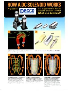
8 We highly recommend that you use a turbocharger which has both an oil and water cooled center section; turbocharger longevity is compromised when only oil is used to cool the turbocharger center Actuator - A spring/diaphragm based mechanism which controls the movement of the wastegate valve. A turbo wastegate is normally closed, forced shut by a compressed spring inside the actuator canister. As pressure is applied to the nipple of the canister, the wastegate shaft moves away from the actuator, swinging open the wastegate Solenoid Valve - An electromagnetic solenoid which controls the air flow from the wastegate actuator to the turbo inlet. This device is normally closed when no voltage is applied. When 12V direct current (DC) voltage is applied, by the drivers in the electronic Control module (ECM), to the wastegate solenoid valve, it fully opens allowing air to pass through the device.
9 A 0% Wastegate Duty Cycle (WGDC) setting will allow the solenoid to stay fully closed; which will force the turbo to run mechanical Boost pressure. A 100% WGDC setting will force the solenoid to stay fully open; which will force the turbo to run maximum Boost Lines - Rubberized or silicone tubes attached to various components in the engine assembly. For this article we will be concerned with the eight attachment points and the four sections of vacuum line plumbing and adapters which we will cover in Chapter Restrictor Pill - A small pill made of brass which contains a precision machined lengthwise hole in the center. This pill restricts the amount of air coming from the J-pipe (which is connected to the compressor housing).Secondary Restrictor Pill - A small pill made of brass which contains a precision machined hole in the center. This pill restricts the amount of air that can be bled from the Boost Control - Also known as an ECM, PCM, EEC, EMS.
10 The Engine Control Unit contains the processors, drivers, and logic which is calibrated to Control the Boost load via wastegate solenoid duty 2006 Cobb Tuning, Inc. All rights 2 PlumbingWe will break down the plumbing of the Factory Boost Control System into 4 sections of vacuum line, 1 adapter, and 8 attachment points. Please look at the following picture where we have the four basic lengths of vacuum line and the 8 attachment points labeled. Three of these lines are pressurized while the vehicle is under load and the one vacuum line which goes to the turbo inlet tube is under a vacuum which is created by the turbo sucking in 2006 Cobb Tuning, Inc. All rights 1 plumbs the nipple on the J-pipe to one end of the 2 plumbs the wastegate actuator to the middle of the T-fitting. This line contains the primary brass restrictor 3 plumbs the other end of the T-fitting to the wastegate solenoid valve.