Transcription of Witton Kramer AC - DC Brakes Thrustors - Brook Crompton
1 Rotating Electrical MachinesWitton KramerAC - DC BrakesThrustorsWitton Kramer - AC, DC Brakes and ThrustorsIndex12345678910111213141516171 8192021 Page - Description of brakesPerigrip - AC Shoe BrakesPerigrip - Installation & MaintenancePM - DC BrakesPM - Extras, Accessories & ModificationsPM - Installation & MaintenancePMA - AC Recified/DC AISE brakePMD - AC Rectified brakeDrum Boring Information & DimensionsAEWK Thrustor Operated brakeMEWK - Thrustor Operated brakeHD Electro-Hydraulic ThrustorsBrake SelectionBasic Drive QuestionnaireCrane brake QuestionnaireCrane/Hoist QuestionnaireCross Traverse QuestionnaireLong Travel QuestionnaireConveyor QuestionnaireWitton Kramer - AC, DC Brakes and Thrustors1 Witton Kramer Products CRANES CONVEYORS PROCESS LINES HOISTS.
2 Theatre SceneryFurnace SkipDocksideBuilding Site MINING ORE UNLOADERS ROLLING MILLS VEHICLE WASH PLANT SKI LIFTS WINCHES GENERAL MACHINERY DRIVESM agnetic Brakes are used for a wide variety of applications. they are simple to use and maintain, and their operation can be controlled in a variety of different ways bymeans of external control equipment. AC Magnetic brake (Perigrip brake )This is a direct acting brake with a laminated magnet system for direct connectionto the AC supply. It has a very fast action in both release and application, and canbe connected direct to a 4 pole direct-on-line cage induction motor without any additional control gear.
3 This long established design is very simple to adjust for lining wear, without tools. Its main intention is that the fast acting magnet clappercan wear at high rates of Kramer manufacture Brakes and Thrustors in their Blackheath site nearBirmingham in England. They supply product on a worldwide basis and have along history of providing products going back over 100 1909 the product scope included separator magnets, Brakes , clutches and solenoids and was expanded shortly to include cranes and hoists. Over the yearscontinued product development added product permutations to the 1950 s brought amalgamation with AEI and English Electric in the UK resulting in the addition of the Perigrip brake and Thrustor designs to the alreadydeveloped PMA, PMD and MTWK Kramer has been an integral part of Brook Crompton in the UK since 1989and continues to manufacture the product in the Blackheath Stroke Magnetic Brakes (Types PM, PMD, and PMA)
4 This is the most popular general purpose drum brake in short stroke brake has a DC magnet, and is operated on AC supplies by an integral or separate short stroke give a fast, precise action. Impact forces and noise are greatlyreduced (especially on the smaller size) compared to the long stroke solenoidbrake, which it has now almost entirely superseded. The brake design is simplified,with a direct linkage, as the magnet force and stroke is equal to the force and (total)stroke of the brake shoes. Wear of pivot pins and linkage is greatly reduced, evenat high rates of operation, thus reducing maintenance and spare can be made suitable for use in adverse environment, eg, high humidity,harsh chemicals, very low temperature and very high temperatures, includingsmoke spill and where flames may envelope the brake .
5 High Integrity versions(category A) are wide range of control is possible to provide a wide variation of brake applicationand release times, for example on a process line the application and release timesof Brakes from 200mm to 500mm dia. can be matched for computer control of ApplicationCranes, hoists, process lines, mill machinery, transfer lines (automotive industry)and general machinery OF MAGNETIC BRAKES2 FeaturesPerigrip magnetic Brakes are suitable for opera-tion on supplies from 110V to 650V. The coilsare continuously rated and insulated to Class B standard.
6 The design incorporates the following features:1)Spring applied; electrically ) Self-adjusting spring-loaded shoe movement ) Adjustment for brake lining using )Self-aligning brake shoes replaceable in a minutes without disturbing the )A welded steel hinged cover protects the complete magnet assembly against dust and damage. 6)Pivot and brake shoe pins are secured by circlips which are easily removed and replaced when )Retaining spring limits the release fitted as )Retarding torque can be reduced without producing hammer blows between magnet and )Double springs fitted as an ) Fibre linings fitted as standard.
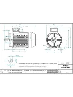
7 Heavy duty asbestos free linings available if required - 680%.11) CSA approved (No. LR10747).ConstructionThe main components are of good quality cast iron. The springs and all machined steel parts are pins are of rolled steel and are secured by linings are cotton fibre based, bonded to entry: 20mm conduit entry to BS4568 on oneside and in American National Pipe thread on theother. brake drums are available as an Perigrip brake with the hinged coverlifted to show the magnet AC Shoe Brakes4 - 12 Witton Kramer - AC, DC Brakes and (dia)inchRettorquelbf ftBCDEFGHJKLMNPQRTA(dia)inchNettMasslbGr ossMasslbVolume packedCubic feetConsumptionVAInrushVAApprox10 in inches3AC Perigrip BrakeInstallation & MaintenanceInstallationMounting Detailsa) When the brake is to be mounted on a drumon an open-ended shaft (such as the non-driveend shaft of a double-shaft-extension motor),rotate the hand release lever to compress thespring and release the brake .
8 Open out the brake shoes by rotating the knurledadjusting nut A in a counter-clockwise locking plunger B must be held withdrawnwhile turning the ) When the brake drum is between a motor andgearbox already mounted on a baseplate, it maybe necessary in some cases to remove the freearm Q to slide the base under the drum. To do this loosen lock-nut E then remove the centering screw D together with its spring. With the plunger B withdrawn, turn the knurled nutA in a counter-clockwise direction and finallyremove it. Remove pivot C and lift out the free arm Q. Slide the brake under the drum and replace thefree arm, pivot, knurled nut and centering screw.
9 Operate the hand release lever P so that thebrake shoes grip the the brake correctly in relation to the drum,ensure the correct centre height ( 1/32 inch or 1mm) and bolt setting of shoe clearancesWith the brake de-energized and with the shoesgripping the brake drum, rotate the knurled adjust-ing nut A until the clapper F can be just closedwith light finger that the spring rod is properly seated in therecess machined in the clapper bearing unscrew the nut A half a turn and proceeduntil the plunger B enters a milled clapper gap is now set approximately mid-way between the home position and the positionof maximum lining wear.
10 Thus ensuring clearancewill exist between the shoes and drum when themagnet closes on energization of the coilEqualizing the shoe clearancesRelease the brake either electrically or by drivinga wedge between the retaining spring and theclapper, to close the air the distance between each shoe and theadjacent side of the necessary adjust the screw D, loosen off thelock-nut E, until the clearances are he off the brake or remove the wedge andcheck that the clapper can now move freely overapproximately half its full fee movement, providing that the clappermoves the spring rod through the operating armsufficiently to release the brake when the coil isenergized, indicates that the brake is correctly is advisable to check the setting of shoe clear-ances after an initial period of work to ensure thatthe brake operates correctly at the working temperature of the brake drum, and during thebedding-in period of the brake for lining wearAs the linings wear.