How to Read a Schematic Diagram Part 2
First Steps in Radio How to Read Schematic Diagram Part 2: The first step toward learning the basic theory of this series is to understand circuit diagrams — the
Tags:
Information
Domain:
Source:
Link to this page:
Documents from same domain
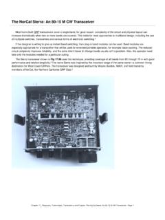
The NorCal Sierra: An 80-15 M CW Transceiver
www.arrl.orgThe NorCal Sierra: An 80-15 M CW Transceiver Most home-built QRP transceivers cover a single band, for good reason: complexity of the circuit and physical layout can

A Home-made Ultrasonic Power Line Arc Detector
www.arrl.orgFrom April 2006 QST © ARRL Figure 2 — Ultrasonic dish assembly. Figure 1 — Simplified block diagram of the ultrasonic detector. at full blast, and the ...

US Amateur Radio Technician Privileges
www.arrl.orgTitle: US Amateur Radio Technician Privileges Author: dszlachetka Subject: Tech Band Chart Keywords: Job #580 Tech Band Chart color only UPDATED 10-29-2015.indd

FSD-218 Relief Emergency · Routine Messages …
www.arrl.orgThe QN signals listed above are special ARRL signals for use in amateur cw nets only. They are not for use in casual amateur conversation. Other meanings that may be used in other services do not apply.
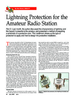
Lightning Protection for the Amateur Radio …
www.arrl.org50 July 2002 also be protected. The method of protection will change, how-ever, since the interface is electronic. Once the peak operating interface voltages are determined, it is relatively straightfor-

Field Day - arrl.org
www.arrl.orgField Day Entry Submission Instructions: Please make certain that your required summary sheet is complete with the following fields filled in:

Registration Form - American Radio Relay League
www.arrl.orgAmateur Radio Emergency Service@ ARES@ Registration Form Name: Cal Sign: Mailing Address: City, state, ZIP code: e-mail address(es): Home phone number:

A Simple yet Precise Function Generator for the …
www.arrl.orgQEX – May/June 2013 7 important role in the generator. A DDS chip like this one builds the waveform using discrete voltage samples whose amplitudes

A Quick Trainer and Field Resource Guide for the …
www.arrl.orgPage 2 This manual is intended to serve as a quick trainer and reference for amateurs deployed in the field for emergency services work, primarily through the ARRL Amateur Radio Emergency Service (ARES).

The Ultimate Transmatch
www.arrl.organd The Ultimate Transmatch BY LEWIS G. MCCOY, *WIICP OME amateurs assume that because they use coaxial feed lines they don't need a Trans- match.
Related documents
WIRING DIAGRAM INFORMATION - Dodge Body …
www.rambodybuilder.comDR _____ WIRING DIAGRAM INFORMATION 8W01 - 9 • Ohmmeter - Used to check the resistance between two points of a circuit. Low or no resistance in a circuit means
IET LCR PRIMER
www.ietlabs.comLCR Measurement Primer 6 of 78 1 What is Impedance? Electrical Impedance (Z), is the total opposition that a circuit presents to alternating current. Impedance changes according to the components in the circuit and the frequency of the
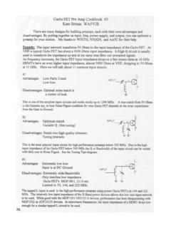
Document1 - Printed Circuit Board Antennas| …
www.wa5vjb.comAdvantages: Extremely versatile, capable of matching most any impedance INPUT Disadvantages: Very large assembly below I GHz Difficult to supply bias voltage
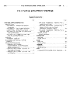
8W-01 WIRING DIAGRAM INFORMATION
www.rambodybuilder.com8w-01 wiring diagram information table of contents page page wiring diagram information description description - how to use wiring diagrams.....2
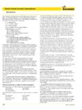
Short Circuit Current Calculations - Cooper Industries
www.cooperindustries.com192 ©2005 Cooper Bussmann Short Circuit Current Calculations Introduction Several sections of the National Electrical Code® relate to proper overcurrent pro-tection. Safe and reliable application of overcurrent protective devices based on

Line to Ground Voltage Monitoring on …
www.facilitiesnet.comLine to Ground Voltage Monitoring on Ungrounded and Impedance Grounded Power Systems December 2010/AT301 by Reza Tajali, P.E. Square D …
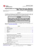
Implementation of a Single-Phase Electronic Watt …
www.ti.comApplication Report SLAA494A– May 2011– Revised May 2013 Implementation of a Single-PhaseElectronic Watt-Hour Meter Using the …
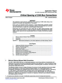
Critical Spacing of CAN Bus Connections (Rev. A
www.ti.com1 Minimum Distance Between Node Connections Application Report SLLA279A–November 2008–Revised January 2009 Critical Spacing of CAN Bus Connections
Related search queries
WIRING DIAGRAM INFORMATION, Circuit, Impedance, Document1, 8w-01 wiring diagram information, Diagram, Short Circuit, Cooper Industries, Ground Voltage Monitoring on, Ground Voltage Monitoring on Ungrounded and Impedance Grounded Power, Implementation of a Single-Phase Electronic Watt, A Single-PhaseElectronic Watt, Meter, Critical Spacing of CAN Bus Connections