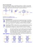
Transcription of How to read an op-amp data sheet
1 How to read an op-amp data sheet : We'll use the lm741 : datasheet to explain the various specifications Input Offset Voltage: The apparent voltage difference between the inputs even when the inputs are shorted together. For the LM741A the average input offset is 2mV with the maximum being 6mV (at 25C). If you have a circuit with a gain of 100 then the output could be off by 200mV (typical) or as much as worst case. Note: The input offset voltage could be as much as depending on the temperature. Input Offset Voltage Drift: How much the input offset changes with temperature. For the LM741A the worst case drift is 15uV/C.
2 So, if your circuit had to operate from 0-60C the input offset could change by 15uV/C * 60C = over the 60C temperature range. Input Offset Voltage Adjustment Range: By connecting a potentiometer to the null pins you can trim the input offset voltage by about +/-15mV. Input Offset Current: Earlier we stated that the input impedance of the ideal op-amp is infinite and that no current entered the input pins. Well, in the real world some current does enter the inputs. In this case the difference between the two input currents is about 20nA (200nA worst case at 25C). Input Bias Current: The current that flows into the input pins to bias the transistors (about 80nA in this case).
3 Note: Some FET op-amps have input bias currents well below 1pA. Input Resistance: The impedance seen looking into the input pins. The LM741A has a minimum input impedance of 2M . Note: This is considered low. Many op-amps have input impedances over 1G . Input Voltage Range: How high or low the voltage at the input pins can be before the op-amp doesn't function properly (or gets damaged). In this case (assuming +/-15V supplies) the inputs should stay below +/-13V. Note: In general Large Signal Voltage Gain: The gain of the op-amp at DC ( low frequency). Earlier we stated that the gain was infinite.
4 In the real world it's large but not infinite. The typical gain is listed as 200V/mV (200,000). Note: Many op-amps have gains over 10^6. Output Voltage Swing: The output can't swing all the way to the power supply rails. The max output voltage also depends on the load current. With a smaller load ( a big load resistor drawing little current) the output can go higher than with a large load ( a small load resistor requiring more current). Most op-amps can swing the output to within a few volts of the power supply rails. Note: There are special op-amps called "Rail-to-Rail" op-amps that can swing the output to within 100mV of the supply rails.
5 These special op-amps are often used in battery-operated products where the power supply may be 6V or less. Output Short Circuit Current: How much current the op-amp can source or sink from the output pin. Note: The output voltage could drop near zero volts when delivering the maximum current. Typically the op-amp can't deliver more than 25mA (but always can deliver at least 10mA). See "Output Voltage Swing" to get an idea of how much voltage you can put across various sized resistors. Common-Mode Rejection Ratio (CMRR): The ratio of the difference gain to the common mode gain. Op-amps are only supposed to amplify the difference between the input pins.
6 In reality, if there is a common voltage (say 1 VDC on both pins) there will be a small gain even though the inputs are the same. The CMRR tells you how good the op-amp is at minimizing this common gain. The lm741 has a worst-case CMRR of 70db and typically it 90 (20db is a factor of 10 so 90db is a ratio of 30,000). Note: Some instrumentation and difference amplifiers can have a CMRR over 110db (300,000). Power Supply Voltage Rejection Ratio (PSRR): This tells you how well the op-amp filters out noise coming through the power pins. Ex: You're using a 12V supply with 100mV of ripple at 120Hz. How will this affect your op-amp circuit?
7 With a PSRR of 96db (inv_log(96/20) = 63,000) the ripple seen by the input will be reduced by a factor of 63,000. So, with a 100mV ripple and a PSRR of 96db the op-amp inputs would see a ripple of If you have a gain of 100 then the output will have a ripple of 160uV even when there is no input to the op-amp . This is why you want to filter you're power supply well and have a good PSRR. Note: The PSRR isn't constant with frequency. It's usually specified at 120Hz but drops off at higher frequencies. Transient Response: This gives you an idea of how fast the op-amp will respond to pulse input (rise time may be the time it takes for the signal to go from 10% to 90% of its final value).
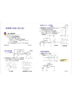
8 Bandwidth (or gain bandwidth product, GBW): The gain as a function of frequency for smaller signals ( the output isn't limited by the slew rate). The lm741 has a GBW around 1 MHz (but not listed in this datasheet). This means that with a 1 MHz input the max gain is one (the gain drops off as frequency increases). Actually the gain is less than one because GBW is defined as the 3db point ( where the voltage drops to of its original value). If the input signal was 100 Khz the max gain would be 10, with a 10 Khz input the max gain would be 100, and so on. Note: The lm741 is considered a slow op-amp . There are op-amps available with a GBW over 1 GHz.
9 Slew Rate: How fast the output can change (measured in V/us). This gives you an idea of the maximum frequency and amplitude signal the output can handle without distortion. The lm741 output typically can only slew at If you have a 10 KHz, 10 Vpeak sine wave on the output the fastest point at which the voltage changes is at the zero crossing. The rate of change dv/dt is (10sin(2*pie*10,000t)) = Since is above the typical spec there is a good chance that the 10 Vpeak, 10 KHz sine wave will have distortion at the zero crossings. To operate without distortion you could lower the voltage or lower the frequency.
10 Again, the lm741 is considered a slow op-amp . You can get op-amps with slew rates in excess of 1000V/us (1V/ns). Supply Current: The current drawn from the power supply with no load on the op-amp . Note: There are low power op-amps available that run on less than 10uA. Usually the faster the op-amp the more power it requires.