Transcription of HP ProLiant DL320e Gen8 v2 Server User Guide - CNET …
1 HP ProLiant DL320e Gen8 v2 Server User Guide Abstract This document is for the person who installs, administers, and troubleshoots servers and storage systems. HP assumes you are qualified in the servicing of computer equipment and trained in recognizing hazards in products with hazardous energy levels. Part Number: 718997-003. July 2014. Edition: 3. Copyright 2013, 2014 Hewlett-Packard Development Company, The information contained herein is subject to change without notice. The only warranties for HP products and services are set forth in the express warranty statements accompanying such products and services. Nothing herein should be construed as constituting an additional warranty. HP shall not be liable for technical or editorial errors or omissions contained herein. Microsoft and Windows are registered trademarks of Microsoft Corporation. Contents Component identification .. 6.
2 Front panel components .. 6. Front panel LEDs and buttons .. 7. Rear panel components .. 7. Rear panel LEDs and buttons .. 8. PCIe riser board slot definitions .. 8. System board components .. 9. DIMM slot locations .. 10. System maintenance switch .. 10. NMI functionality .. 11. Drive numbering .. 11. Hot-plug drive LED definitions .. 11. FBWC module LED definitions .. 12. Fan locations .. 13. 14. Power up the Server .. 14. Power down the Server .. 14. Extend the Server from the rack .. 14. Remove the Server from the rack .. 16. Remove the security bezel (optional).. 17. Remove the access panel .. 17. Install the access panel .. 17. Remove the air baffle .. 18. Install the air baffle .. 19. Remove the PCI riser 19. Install the PCI riser cage .. 20. 22. Optional installation services .. 22. Optimum 22. Space and airflow requirements .. 22. Temperature requirements .. 23. Power requirements.
3 24. Electrical grounding requirements .. 24. Server warnings and 24. Rack warnings .. 25. Identifying the contents of the Server shipping 26. Installing hardware options .. 26. Installing the Server into the rack .. 26. Installing the rack rail cable ties .. 27. Powering on and selecting boot options .. 28. Installing the operating system .. 29. Registering the 29. Setting up the HP PS1810-24G Switch (optional) .. 30. Hardware options 34. Contents 3. Introduction .. 34. Security bezel option .. 34. Drive options .. 34. Drive installation guidelines .. 35. Installing a non-hot-plug drive .. 35. Installing a hot-plug drive .. 36. Controller options .. 37. Installing a storage controller .. 38. Installing the FBWC module and capacitor pack .. 39. Optical drive option .. 42. Memory options .. 45. HP SmartMemory .. 45. DIMM identification .. 45. Single-rank and dual-rank DIMMs .. 46. Memory subsystem architecture.
4 46. ECC memory .. 46. General DIMM slot population guidelines .. 47. Installing a 47. Expansion board options .. 48. Internal USB connector 50. HP Trusted Platform Module option .. 51. Installing the Trusted Platform Module board .. 52. Retaining the recovery 54. Enabling the Trusted Platform Module .. 54. Cabling .. 55. Cabling overview .. 55. Storage cabling .. 55. Two-bay LFF non-hot-plug drive cage cabling .. 55. Two-bay LFF hot-plug drive cage cabling .. 56. Four-bay SFF hot-plug drive cage cabling (AC power supply) .. 57. Optical drive 60. Power supply cabling .. 61. HP 250 W Integrated Power Supply 61. HP 300 W Integrated Power Supply 62. HP 750 W CS -48 V DC Power Supply (with PDB) cabling .. 64. Internal USB cabling .. 64. Front I/O board cabling .. 65. Software and configuration utilities .. 66. Server mode .. 66. Product 66. HP iLO .. 66. Active Health System .. 67. Integrated Management Log.
5 68. HP Insight Remote Support software .. 68. Scripting Toolkit for Windows and Linux .. 69. Intelligent Provisioning .. 69. HP Insight Diagnostics .. 70. Erase Utility .. 70. HP Service Pack for ProLiant .. 71. HP Smart Update Manager .. 71. HP ROM-Based Setup Utility .. 71. Using RBSU .. 72. Contents 4. Auto-configuration process .. 72. Boot options .. 73. Configuring AMP modes .. 73. Re-entering the Server serial number and product ID .. 73. Utilities and features .. 74. Array Configuration Utility .. 74. HP Smart Storage 75. Option ROM Configuration for 75. ROMPaq 75. Automatic Server Recovery .. 76. USB support .. 76. Redundant ROM support .. 76. Keeping the system current .. 77. Access to HP Support Materials .. 77. Drivers .. 77. Software and firmware .. 77. Version control .. 77. HP operating systems and virtualization software support for ProLiant servers .. 78. HP Technology Service Portfolio.
6 78. Change control and proactive notification .. 78. Troubleshooting .. 79. Troubleshooting resources .. 79. System battery 80. Regulatory information .. 82. Safety and regulatory compliance .. 82. Belarus Kazakhstan Russia 82. Turkey RoHS material content declaration .. 83. Ukraine RoHS material content declaration .. 83. Warranty information .. 83. Electrostatic discharge .. 84. Preventing electrostatic discharge .. 84. Grounding methods to prevent electrostatic discharge .. 84. Specifications .. 85. Environmental specifications .. 85. Server specifications .. 85. Power supply specifications .. 85. HP 250 W Integrated Power Supply .. 85. HP 300 W Integrated Power Supply .. 86. HP 750 W CS -48 V DC Power Supply (94% efficiency) .. 86. Support and other resources .. 88. Before you contact HP .. 88. HP contact information .. 88. Customer Self Repair .. 88. Acronyms and abbreviations.
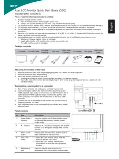
7 96. Documentation feedback .. 100. Index .. 101. Contents 5. Component identification Front panel components Two-bay LFF drive model Item Description 1 Optical drive blank 2 Serial number/iLO information pull tab*. 3 USB connectors 4 LFF drives ( cm, in). * The serial number/iLO information pull tab is double-sided. The top side shows the Server serial number, and the reverse side shows the default iLO account information. The same information is printed on a label attached to the chassis. Four-bay SFF drive model Item Description 1 Optical drive blank 2 Serial number/iLO information pull tab*. 3 USB connectors 4 SFF drives ( cm, in). * The serial number/iLO information pull tab is double-sided. The top side shows the Server serial number, and the reverse side shows the default iLO account information. The same information is printed on a label attached to the chassis. Component identification 6.
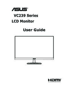
8 Front panel LEDs and buttons Item Description Status 1 Health LED Solid green = Normal Flashing amber = System degraded Flashing red (1 Hz/cycle per sec) = System critical Fast-flashing red (4 Hz/cycles per sec) = Power fault*. 2 NIC status LED Solid green = Link to network Flashing green (1 Hz/cycle per sec) = Network active Off = No network activity 3 UID button/LED Solid blue = Activated Flashing blue (1 Hz/cycle per sec) = Remote management or firmware upgrade in progress Off = Deactivated 4 Power On/Standby button Solid green = System on and system power LED Flashing green (1 Hz/cycle per sec) = Performing power on sequence Solid amber = System in standby Off = No power present**. * To identify components in a degraded or critical state, see the iLO/BIOS logs and the Server troubleshooting Guide . ** Facility power is not present, power cord is not attached, no power supplies are installed, power supply failure has occurred, or the power button cable is disconnected.
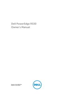
9 Rear panel components Item Description 1 Slot 2 PCIe3 x8 (4, 1). 2 Slot 1 PCIe3 x16 (8, 4, 1). 3 Integrated power supply 4 NIC 1/shared iLO 4 connector 5 Video connector 6 NIC connector 2. 7 USB connectors 8 Dedicated iLO 4 connector 9 USB connectors Component identification 7. Rear panel LEDs and buttons Item Description Status 1 NIC link LED Solid green = Link exists Off = No link exists 2 NIC status LED Solid green = Link to network Flashing green (1 Hz/cycle per sec) = Network active Off = No network activity 3 Power supply LED Solid green = Normal Off = One or more of the following conditions exists: Power is unavailable Power supply failed Power supply is in standby mode Power supply error 4 UID button/LED Solid blue = Activated Flashing blue (1 Hz/cycle per sec) = Remote management or firmware upgrade in progress Off = Deactivated PCIe riser board slot definitions The riser board slots transfer rate is the same for all supported processor models.
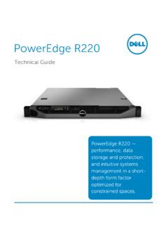
10 Both slots will run in PCIe3. (8 GT/s) rate. Slot number Type Length Height Connector link width Negotiable link width 1 PCIe3 Half Full x16 x8. 2 PCIe3 Half Half x8 x4. Component identification 8. System board components Item Description 1 PCI riser connector*. 2 TPM connector 3 microSD card slot 4 Processor socket 5 Fan connector 2. 6 Fan connector 1. 7 DIMM slots 8 4-pin power supply connector 9 System battery 10 Front I/O module connector 11 24-pin power supply connector 12 26-pin PDB connector 13 SATA connector 14 Mini-SAS connector 15 Fan connector 3. 16 Internal USB connector 17 System maintenance switch * For more information on the riser board slots supported by the onboard PCI riser connector, see "PCIe riser board slot definitions (on page 8).". Component identification 9. DIMM slot locations DIMM slots are numbered sequentially (1 through 4) for the processor. The supported AMP modes use the letter assignments for population guidelines.