Transcription of HS25 Incremental Optical Encoder - BEI Sensors
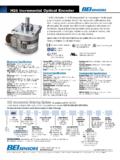
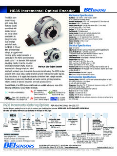
1 hs25 Incremental Optical Encoder Mechanical Specifications Shaft Bore: , , , , dia. and under are supplied with insulating sleeves. Allowable Misalignment: : on mating shaft from shaft end Bore Runout: The hs25 combines the Starting Torque at 25 C: Through shaft version (SS) = 7 in-oz (max);. rugged, heavy-duty features Blind shaft version (BS) = 4 in-oz (max). usually associated with Bearings: 52100 SAE high carbon steel Shaft Material: 6061-T6 aluminum alloy shafted encoders into a Bearing Housing: Die cast aluminum with protective finish hollow-shaft style. Its design Cover: Die cast aluminum with protective finish includes dual bearings and Bearing Life: X 109 revs (25,000 hrs at 2500 RPM). shaft seals for NEMA 4, 13 Maximum RPM: 6,000 RPM (see Frequency Response, below). Moment of Inertia: 17 X 10 4 oz-in-sec2. and IP65 environmental Weight: 9 oz typical ratings, a rugged metal housing, and a cable gland. Electrical Specifications Code: Incremental Output Format: 2 channels in quadrature, 1/2 cycle index gated This low-profile design, with negative B channel just 2 deep, is easily mounted on a through shaft.
2 Securing the Encoder to the shaft Cycles per Shaft Turn: up to 2048 (see table A, this page). is simple with a collet-style single screw clamp. The optional anti-rotation tether block Supply Voltage: 5 to 28 VDC available (see note 5). maintains housing stability during operation. The hs25 is designed to accommodate Current Requirements: 100 mA typical + output load, 250 mA (max). Voltage/Output: (see note 5). shafts up to 3/4 in diameter. With optional insulating inserts, it can be mounted on 15V/V: Line Driver, 5 15 VDC in, Vout = Vin smaller diameter shafts. Applications include motor feedback and vector control, paper 28V/V: Line Driver, 5 28 VDC in, Vout = Vin 28V/5: Line Driver, 5 28 VDC in, Vout = 5 VDC. converting and printing industries, robotic control, web process control along with many 28V/OC: Open Collector, 5 28 VDC in, OCout other applications. Protection Level: Reverse, overvoltage and output short circuit Frequency Response: 100 kHz (see note 7).
3 Output Terminations: (see table 1, back page). Special Models of the hs25 Incremental Encoder are available with one or more of the fol- Note: Consult factory for other electrical options lowing certifications. Consult factory for details. Environmental Specifications Enclosure rating: NEMA 4 & 13 (IP65) when ordered with shaft seal EN 55011 Standards Class I, Group A,B,C and a cable gland. and EN 61000-6-2 Class II Group E, F & G Temperature: Operating, 0 to 70 C; extended temperature testing up to 85 C available (see note 8); Storage, -25 to 90 C unless extended tem- UL Canadian Standards perature option called out UL C Class I, Zone 0, Group IIC Shock: 50 g's for 11 msec duration Vibration: 5 to 2000 Hz @ 20 g's CENELEC Humidity: 98% RH non-condensing Class I, Div 2, Group A,B,C . II 1 G Ex ia IIB/IIC T4 NOTES & TABLES: All notes and tables referred to in the text can be found Class II, Div 2, Group F & G. II 3 G Ex nA IIB T4 Gc on the back of this page.
4 hs25 Incremental Ordering Options FOR ASSISTANCE CALL 800-350-2727. Use this diagram, working from left to right to construct your model number (example: HS25F-62-R1-SS-1024-ABZC-28V/V-SCS18). All notes and tables referred to can be found on the back of this page. hs25 . TYPE: SHAFT BORE: SHAFT SEAL NO. OF CHANNELS: VOLTAGE/OUTPUT: HAZARDOUS SPECIAL. HS = Hollow Shaft CONFIGURATION: A = Single Channel AREA RATINGS: FEATURES: 75 = 28V/V = 5 28 Vin/out 25 = Encoder SS = Through Shaft Rubber Seals AB = Dual Quad. Ch. 28V/5 = 5 28 Vin/5 Vout Blank = None S = Special Diameter 62 = . BS = Blind Shaft Rubber Seal ABZ = Dual with Index 28V/OC = 5 28 Vin/OCout EX = Intrinsically Safe features specified 50 = . FS = Through Shaft Felt Seals AZ = Single with Index See note 5 NI = Non-Incendive on purchase order 37 = Contact factory for (consult factory). BFS = Blind Shaft Felt Seal See note 3. voltage options See note 6. TETHER: See note 2. X= HOUSING CONFIG: CYCLES PER COMPLEMENTS: Express F = Standard Blank = None OUTPUT TERMINATION: TURN: C = Complementary Encoder R1 = Tether Block SM12 = MS3112E12-10P.
5 (Enter Cycles) Outputs and Pin SCS = Shielded, Jacketed Cable with Cable See table A See note 4 gland seal and cable length in inches, R2 = Tether Arm ( SCS18 = 18 inches). SCS18-M18 = SM18 connector on end of cable EXPRESS ENCODERS Items highlighted with . are standard Express Encoders and ship in one to three days. with length specified in inches ( SCS18-M18). M18 = MS3101F18-1P. See table 1 and note 9. specification No. 02065-001 These commodities, technology or software if exported from the United States must be in accordance with the Bureau of Industry, and Security, Export Administration regulations. Diversion contrary to law is prohibited. hs25 Incremental Optical Encoder Dimensions Notes 1. The typical hollow shaft product is supported by, and clamped to, the driving Thru Shaft Version shaft. A flexible tether is used to keep the housing from rotating. 2. The rubber shaft seal is recommended in virtually all installations. The most common exceptions are applications requiring a very low starting torque or those requiring operation at both high temperature and high speed.
6 For these excep- tions, a felt shaft seal is recommended. Felt seals require very low starting torque and can virtually eliminate frictional heat. Encoders ordered with felt shaft seals will have an enclosure rating of IP50 and will have less than 1/10th the Starting Torque specified under Mechanical Configurations. 3. Non-standard index widths and multiple indices are available by special order. Consult factory. 4. Complementary outputs are recommended for use with line driver type (source/sink). outputs. When used with differential receivers, this combination provides a high degree of noise immunity. 5. Output IC's: Output IC's are available as either Line Driver (LD) or NPN Open R1 Tether Block Collector (OC) types. Open Collectors require pull-up resistors, resulting in higher Blind and Pin Shaft output source impedance (sink impedance is similar to that of line drivers). In Version general, use of a Line Driver style output is recommended. Line Drivers source or sink current and their lower impedance mean better noise immunity and faster switching times.
7 Warning: Do not connect any line driver outputs directly to circuit common/OV, which may damage the driver. Unused outputs should be isolated and left floating. Our applications specialists would be pleased to discuss your TOLERANCES: system requirements and the compatibility of your receiving electronics with Line .XX= , .XXX= Driver type outputs. 28V/V: Multi-voltage Line Driver (7272*): 100 mA source/sink. Input voltage 5 to M12 28 VDC +/- 5% standard (Note: Vout = Vin). This driver is TTL compatible when R2 Tether Arm used with 5 volt supply. Supply lines are protected against overvoltage to 60 volts and reverse voltage. Outputs are short circuit protected for one minute. Supply current is 120 mA typical (plus load current). This is the recommended replace- ment for 3904R and 7406R open collector outputs with internal pullup resistors. It is also a direct replacement for any 4469, 88C30, 8830 or 26LS31 line driver 28V/5: Multi-voltage Line Driver (7272*): 100 mA source/sink.
8 Input voltage 5 to 28. VDC +/- 5% standard, internally regulated with 5V (TTL compatible) logic out. Supply lines are protected against overvoltage to 60 volts and reverse voltage. Outputs are short circuit protected for one minute. Supply current is 90 mA typical (plus load cur- rent). 15V/V: Multi-voltage Line Driver (4469*): 100 mA source/sink. Input voltage 5 to 15 VDC +/- 5% standard (Note: Vout = Vin). TTL compatible when used with 5. volt supply. Supply lines are protected against overvoltage to 60 volts and reverse voltage. Outputs are short circuit protected for one minute. Supply current is 90. mA typical (plus load current). This is a direct replacement for the 4469 Line Table A Table 1 M18 CONNECTOR M12 CONNECTOR. Driver. 28V/OC: NPN Open Collector (3904*, 7273*). Current sink of 80 mA max. Current hs25 Disc Resolutions sourced by external pull- up resistor. Output can be pulled up to voltage other than Incremental Output PIN. A. CHANNEL. A. PIN.
9 A. CHANNEL. A supply voltage (30 V max). Input voltage 5 to 28 VDC +/- 5% standard. Supply 10 12 60 88 100 122 250 360 Terminations B B B B current is 120 mA typical. This replaces prior IC's with designations of 3904, 7406, 500 512 1000 1024 2000 2048 The connector style will C Z C Z 3302, 681 and 689. 5V/OCR, 15V/OCR, 24V/OCR: Open Collector (3904R*, determine pinouts. For D +V D +V 7406R*, 7273R*): Current sink of 70 mA max. Includes internal pull-ups sized Other resolutions available consult factory. E E . example, an Encoder at approximately 100 ohms/volt. Max current source is 10 mA. Supply current Figure 1. F 0V F 0V. with ABC channels and is 100 mA typical, 120 mA with internal pull-ups. The 5V/OCR, 15V/OCR and G CG G CG. an M18 connector uses H A. 24V/OCR are often replaced by the 28V/V in system upgrades. H A. Output Waveform the table to the right. I B J B 3904, 3904R, 4469, 5V/V, 5V/OC, 5V/OCR, 9V/OC: Intrinsically safe line J Z K Z driver and open collector outputs.
10 These drivers are specific to intrinsically safe M14 CONNECTOR M16 CONNECTOR CHANNELS DESIGNATED IN MODEL NO. encoders, and are installed per the appropriate control drawings listed in Table PIN PIN ABZ ABC on page 48. HI E A A A. D B B B. 6. Special S at the end of the model number is used to define a variety of non- LO. C C Z A. standard features such as special shaft lengths, voltage options, or special testing. B D +V (SUPPLY VOLTAGE) Please consult the factory to discuss your special requirements. F E B. 7. Higher frequency response may be available. Please consult with the factory. A F 0 V (CIRCUIT COMMON). G CASE GROUND (CG) (except H20) 8. Extended temperature ratings are available in the following ranges: WIRE COLOR DA 15P CHANNELS DESIGNATED IN MODEL NO. -40 to 70 C, -40 to 85 C, 20 to 105 C and 40 to 105 C depending on (22 AWG) CONNECTOR ABZ ABC ABZC the particular model. Some models can operate down to -55 C. Extended YEL 13 A A A temperature ranges can affect other performance factors.