Transcription of Hydraulic and pneumatic actuators - Anasayfa
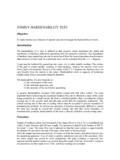
1 Actuation systemsActuation systems are the elements of control systems which are responsible for transforming the output of a microcontrollers or microprocessor or control system into a controlling action on machine or device eg. pneumatic , Hydraulic , mechanical, and electrical actuation systems SensorsActuatorCommand SignalSensing signalMicroprocessororMicrocontrollerPLA NT(Robot, Autonomous Guided vehicle, Numerical Controlled Machine,Vehicle engines, Consumer products, Conveyor systems, Assembly systems,Cranes, Defense equipments, Air craft engines, Other machines, consumer products, etc)Control codeParameter, variablesActuationMechanical componentsPneumatic & Hydraulic actuation systems pneumatic deals with air pressure Hydraulic deals with fluid motion and pressureTypical Hydraulic Power System The pressure relief valve is to release the pressure if it rises above a safe level, The accumulator is to smooth out any short term fluctuations in the output oil pressure The pump pumps oil from a sump through a non return valve and an accumulator to the system, from which it return to the a Hydraulic system, pressurized oil (fluid)
2 Is provided by a pump driven by an electrical Hydraulic Power System The Accumulator Work Accumulator is a container in which the oil is held under pressure against an external force, which involves gas within a bladder in the chamber containing the Hydraulic fluid If the oil pressure rises then the bladder contracts increase the volume the oil can occupy and so reduces the pressure. If the oil pressure falls the bladder expands to reduce the volume occupied by the oil and so increases its pressure. Typical pneumatic Power SystemIn pneumatic power system an electric motor drives an air compressor. Since the compressor increase the temperature of the air, there likely to be a cooling system and to remove contamination and water from the air, a filter with water trap is air receiver increases the volume of air in the system and smoothes out any short-term pressure fluctuations.
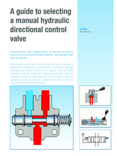
3 A pressure relief valve provides protection against the pressure in the system rising above a safe level. The air inlet to the compressor is likely to be filtered and via a silencer to reduce the noise level. Directional Control Valves-1 pneumatic and Hydraulic systems use directional control valves to direct the flow of fluid through a system; its ON/OFF devices either completely open or closed They might be activated to switch the fluid flow direction by means of mechanical, electrical or fluid pressure signalDirectional Control Valves-2 Common Types:1-Spool valve:Move horizontally within the valve body to control flow 2-Rotary spool valve: have the same idea, when rotates opens and closes portsDirectional Control Valves-3 3-Poppet valve: This valve is normally in closed condition.
4 In this valve, balls, discs or cones are used in conjunction with valve seats to control the flow. When the push-button is depressed, the ball is pushed out of its seat and flow occurs as a result of port 1 being connected to port 2. When the button is released, the spring forces the ball back up against its seat and so closes off the Control Valves-4 Directional valvesFree flow can only occur in one direction through the valve, flow in the other direction is blocked by Symbols-1 The valve symbol consists of square for each of its switching positions. Thus for the shown poppet valve there are two positions, one with the button not pressed and one with it pressed.
5 Thus two positions valve will have two squares, a three positions valve have three headed lines are used to indicate the directions of flow in each positionclosed flow lines; blocked offFigure (a) Flow path, (b) flow shut-off, (c) initial connectionsPorts are labeled1 (or P) for pressure supply3 (or T) for Hydraulic return port3 or 5 (or R or S) for pneumaticexhaust ports2 or 5 (B or A) for output portsValve Symbols-2 Symbols of Valve actuationIt indicates the various ways the valves can be actuated (see Fig)Valve actuation symbolsBolton, Mechatronics, 4thedition Pearson limited 2008 Valve Symbols-3 solenoid operated spool valveThe valve is actuated by a current passing through the solenoidand return to its original position by spring Fig.
6 Shows the symbol for a 3/2 valve, the connection is shown for initial state 1(P) is connected to 2(A); 3(R) is closed. When the solenoid is activated, it gives the state indicated by the symbols used in the square to which it is attached, we now have 1(P) closed and 2(A) connected to 3(R). When current through the solenoid ceases the spring pushes the valve back to its initial Symbols-4 The spring movement gives the state indicated by the symbols used in the square to which it is 3/2 valveBolton, Mechatronics, 4thedition Pearson limited 2008 a simple example of an application of valves in a pneumatic lift systemValve Symbols-5 Bolton, Mechatronics, 4thedition Pearson limited 2008 Pilot-operated valvesIn pilot operated system one valve is used to control a second valve.
7 In the Fig the pilot valve is small size and can be operated manually or by a solenoid . It is used to overcome when the force required to move the ball shuttle in a valve can often be too large for manual or solenoid operationBolton, Mechatronics, 4thedition Pearson limited 2008 Pressure control valve-1 Three main types1- Pressure limiting valve:used to limit the pressure in a circuit to below some value2- Pressure regulation valve: used to control the operating pressure in a circuit and maintain it at constant control valve-23-Pressure sequence valve: are used to sense the pressure of an external line and give a signal when it reaches some preset value.(a) Pressure sequence valve symbol, (b) a sequential systemHydraulic/ pneumatic linear actuators , Cylinders Both Hydraulic and pneumatic actuators have the same principles, differences being in size The cylinder consists of a cylindrical tube along which a piston/ram can slide They are of two types: Single acting and double actingCylinders:Single acting Single acting: the control pressure is applied to one side of the pistonCylinders.
8 Single actingControl of a single-acting cylinder with (a) no current through solenoid , (b) a current through the solenoidWhen a current passes through the solenoid , the valve switches position and pressure is applied to move the piston along the cylinder. When current ceases, the valve reverts to it is initial position and the air is vent from the :Double acting Are used when control pressure are applied to both side of the piston. A different in pressure between the two sides results in motion of the piston (No spring). Cylinders: Double actingControl of a double-acting cylinder with solenoid , (a) not activated, b) activatedCurrent through one solenoid causes the piston to move in one : Example A Hydraulic cylinder to be used to move a work piece in a manufacturing operation through a distance of 250 mm in 15 s.
9 If a force of 50 KN is required to move the work piece, what is the required working pressure and Hydraulic liquid flow rate if a cylinder with a piston diameter of 150 mm is available. Solution: A= r2= ( )2= m2 The working pressure = F/A = 50x103 MPa The speed of a Hydraulic cylinder = flow rate of the liquid through the cylinder v=Q/A Flow rate= ( )= sequencingMany pneumatic or Hydraulic control systems may require a sequence of extension and retraction of cylinders to occur. we have two cylinders: A and BIf the start button pressed;{ piston A extends;If fully extended then piston B extends;If both A and B fully extended thenPiston A retracts;If A is fully retracted have piston B retract}Cylinder sequencing5-If A is fully retracted have piston B retract1- If the start button pressed;2-piston A extends;3-If A fully extended then piston B extends;4- If both A and B fully extended then Piston A retractsProcess Control Valve used to control the fluid flow rate A common form of pneumatic actuator used with process control valve is the diaphragm actuator.
10 The diaphragm is made of rubber which sandwiched in it is centre between two circular steel discs. The effect of changes in the input pressure is to move the central part of the diaphragm. The force F on the shaft is the force that acting on the diaphragm= P x AWhere P: gauge pressure =Control pressure-atmospheric pressureA: diaphragm areaThe restoring force is provided by spring, so kx=PAProcess Control Valve Valve bodies & Plugs Fig shows a cross section of valve for the control of rate of flow of a fluid. The plug restricts the fluid flow and so its position determines the flow rateProcess Control Valve Forms of Valve Body & Plug Single seated: closed more tightly but required more force Double seated: less force is required, less tightlyProcess Control Valve Shape of the Plug: determines the relation between the stem movement and the effect on the flow rate 3 types are commonly used Fig shows the relation between the stem displacement & flow rate as % of maximum Rotary actuators A linear cylinder can, with suitable mechanical linkage be used to produce rotary movement through angles less than 3600 Another alternative is shown in Fig.