Transcription of Lateral Earth Pressures and Retaining Walls
1 Lateral Earth Pressures and Retaining Walls . are usually built to hold back soil mass Retaining Walls Types Reinforcement Reinforcement Assistant Prof. Berrak Teymur 1. Gravity 2. Semi-Gravity 3. Cantilever Headers Filled with soil Strectcher Counterfort 5. Crib Wall Face of wall 4. Counterfort Design Basic soil parameters;. Unit weight of soil Angle of friction Cohesion Then the Lateral pressure distribution will be known. There are 2 phases in the design of a Retaining wall;. The Retaining wall is checked for stability: overturning, sliding and bearing capacity failures. Each component of the Retaining wall is checked for adequate strength and the steel reinforcement. Empirical relationships related to the design of Walls (Azizi, 2000).
2 1. Lateral Earth pressure If the water table is located at depth z<H, the at-rest pressure diagram will be as shown. At Rest q q K0 q h = K 0 v + u K0 q = sat- w 1. v K0: coefficient of at- At z=0, h=K0 v=K0q c z H1 c At z=H1, 2 rest Earth pressure z K0 (q+ H1). H P1 . h P0 GWT h=K0 v=K0(q+ H1). H. P2 sat At z=H2, c u H/2 H2 h=K0 v=K0(q+ H1+ 'H2). z' h H/3. K0 (q+ H). 1 K0 (q+ H1+ H2) wH2. The total force: P0 = P1 + P2 = qK0 H + H 2 K0 where K 0 = 1 sin . 2. H H for normally 1 1 1. P 1 . 2.. + P 2 . 3.. consolidated soil P0 = K 0 qH1 + K 0 H12 + K 0 (q + H1 ) H 2 + K 0 H 22 '+ H 22. z = 2 2 2. P 0. Rankine Active Earth pressure Relating the principal stresses for a Mohr's circle that touches the Mohr-Coulomb failure envelope.
3 Wall movement to left . x 45+ /2 45+ /2 1 = 3 tan 2 45 + + 2c tan 45 + . 2 2 . v 1= v and 3= a z z c . H. Thus v = a tan 2 45 + + 2c tan 45 + . h 2 2 . a= vKa-2c Ka The Mohr's circle will touch the Rotation of wall Mohr-Coulomb failure envelope where Ka=tan2(45- /2); Rankine active pressure coefficient about this point representing the failure condition in However the active Earth pressure condition will be reached only if the wall is the soil mass. h= a, where a is the allowed to yield' sufficiently. Rankine active pressure . The amount of outward displacement of the wall necessary is about to The Mohr-Coulomb failure envelope is defined by; for granular soil backfills and about to for cohesive = c + tan backfills. 2.
4 The active force per unit length of the wall, Pa will be Coulomb's Active Earth pressure inclined at an angle of to the normal to the back face of the wall. is the angle, the 1. back face of the Retaining wall Pa = K a H 2. makes with the 2. horizontal. is the angle that the backfill makes - with the Pa horizontal. is the angle of W. friction between R the soil and the H: height of wall 1- wall. The value of the wall friction angle, is between /2. and 2 /3. Rankine Passive Earth pressure Rankine Passive Earth pressure Direction of wall movement x The horizontal stress h at 45- /2. this point is referred to as the Rankine passive v 45- /2. z pressure , z c The magnitude of the wall H h p= vKp+2c Kp movements, x required Soil Type Dense sand x (for passive condition).
5 To develop failure under where Kp=tan2(45+ /2); Loose sand passive conditions are;. Rankine passive Earth Stiff clay pressure coefficient Soft clay Rotation of wall about this point 3. Rankine Active and Passive Earth pressure for Coulomb's Passive Earth pressure Inclined Granular Backfill sin 2 ( ) . 1 Kp =. Pp = H 2 K p sin( + ) sin( + ) . 2. 2 sin sin( + ) 1 . 2. 1. sin( + ) sin( + ) . c=0 Pa = H 2 K a a = zK a 2. Kp: Coulomb's passive pressure z Pa K = cos cos cos cos . coefficient a 2 2. a Range of Wall H cos + cos cos . 2 2. Friction Angle Backfill material ( ) 1. H/3 Pp = H 2 K p Gravel 27-30 2. Coarse sand 20-28. Fine sand 15-25 cos + cos 2 cos 2 . Kp = cos . Stiff clay 15-20 cos cos 2 cos 2 . Silty clay 12-16.
6 Retaining Wall Stability Application of Lateral Earth pressure Theories 1) Safety Against Overturning (Rotational stability) : to Design Cantilever . Gravity Consider forces WC, WS, PV, PH. Ws PV. PA Take moment C' (TOE). Ws Ws H' H' Wc H PA H PA. WC WC. clockwise : resisting (MR) (WC, PH. H/3 . H/3. WS, PV) :overturning (MO) (PH). C. B. if not increase the base B' ;use piles ;increase wall dimensions. Fs=2 (for cohesive backfill) and (for granular backfill). 4. Retaining Wall Stability 2) Safety Against Base Sliding : 1. If base key : Pp = 2 D1 2 K p + 2 c 2 D1 K p 2. use reduced c2 and 2 ( design=(0,5~0,67) 2 , cdesign= =(0,5~0,67) c2). Driving Force : PH if not increase B ; provide key ;stronger backfill (import soil.
7 Ignore : PV expansive) ; install tiedown anchors Resisting force :R. Ws Install tieback anchors PV. R = c2 B + ( V ) tan 2 + Pp Wc PA Use stronger . c2 B + ( V ) tan 2 + Pp backfill Fs = 1 .5 PH. PA cos D. D1 c1, 1, 1. Extend heel R c2, 2, 2 Provide key B Install tiedown anchors(if large). 3) Bearing capacity failure. Fs=3=qu/qmax 4) Deep Seated Shear Failure : Base Pressures : qall : allowable bearing capacity of foundation soil Sum of vertical Ws PV forces Wc PA M R M D. Wc+Ws+Pv x=. V. PH V e Possible failure B surface e= x Weak soil 2 CONVENTIONAL. ANALYSIS. A A V 6e qmax = (1 ). B x min B *1 B. qmin B/2. qmax 5) CHECK FOR SETTLEMENTS (Conventional) : B 6) REINFORCEMENT DESIGN (Structural Design) : qmin > 0 (no tension).
8 Qmax < qall 5. Gravity Retaining -Wall Design for Comments Relating to Stability Earthquake Conditions Coulomb's active Earth pressure theory can be extended to The Lateral force of the backfill will depend on (Casagrande, take into account the forces caused by an earthquake. 1973); horizontal EQ acc .comp . kh =. Effect of temperature (freeze and thaw), acc .due to gravity , g kvW . Groundwater fluctuation, c=0 vertical EQ acc .comp . khW kv =. Readjustment of the soil particles due to creep and g H. prolonged rainfall, W P = 1 H 2 (1 k ) K. ~0,6H AE v Tidal changes, 0,5H Pae 2 AE. sin 2 ( + ). Heavy wave action, K AE = 2. sin( + ) sin( ) . Traffic vibration, k cos sin 2 sin( ) 1 + . = tan 1 h sin( ) sin( + ) . Earthquakes.
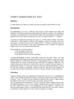
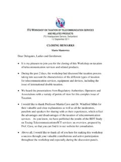
9 1 kv . Drainage from the Backfill of the Retaining Sheet Pile Walls Wall are widely used for both large and small waterfront structures. used for Beach erosion protection Stabilizing ground slopes Shoring Walls of trenches and other excavations and for cofferdams. Bowles, 1997. 6. Sheet Pile Walls Sheet Pile Walls Types: Cantilever Sheet Pile Walls Sheet Piles can be categorised as: Wooden Precast concrete a) Cantilever -Used for small Retaining height (20 ft 6 m above dredge line). b) Anchored Permanent : sands, gravels Steel Construction Methods: Temporary : other soils 1. Backfilled structure -Stability of cantilever sheet pile wall : due to passive 2. Dredged structure resistance developed below the lower soil surface Sheet pile connections: a) Thumb and finger type b) Ball and socket type Cantilever Sheet Pile Walls Anchored Sheet Pile Walls Failure Additional support to sheet pile Walls can be given by backs mode h Active Active (anchored) near the top of the wall (Used in deep excavation &.
10 Water front construction ). Dredge Passive d line 0 0 R Tie Rod A. 0 (steel cables). Active Passive Passive h *fixing moment at 0 Design Idealisation Net Passive Resistance below 0' : given with R' . Bending design : Mc= 0 determine d'. d Moment Then d' is increased arbitrarily by %20 to allow for simplification Passive Active Diagram of procedure . ( : embedment). Fh= 0 determine R. ( Check Pp R / over 0,2d ) Note: depth of tension crack < depth of tie. 7. Anchored Sheet Pile Walls Sheet Piles with Anchors When there is a deep excavation DESIGN PROCEDURE: Anchor A A. 1- Calculate Active & Passive Pressures in terms of h (unknown) depth of embedment , d' . 2- Usually Fs=2 is applied to passive Pressures 3- Take MA =0 ; obtain cubic equation in terms of d'.