Transcription of ICO4-PST Electromagnetic actuated, directly …
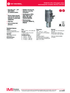
1 ICO4-PST Electromagnetic actuated , directly controlled 04/16en policy is one of continued research and development. We therefore reserve the right to amend, without notice, the specifications given in this document. (2015 - 5330e) 2015 Thompson Valves Ltd. >3/2 Smart solenoid poppet valves; 1/4 NPT .. 3/4 NPT, G1/4 .. G3/4 >Partial Stroke Testing integrated into the ICO4 valve >Dramatically reduces engineering requirements >Up to Cv removes need for additional QEV s and Pilot valves >Offers SIL 3 performance as 1oo1 >Always gives maximum possible Diagnostic Coverage, thus facilitating maximum possible proof test intervalsTechnical data - standard modelsSymbolPort sizeCv (kg)(lbs)
2 321PC3213213 PCPC1/4 NPT0,81/2 NPTNBR6,714,71Y413AA1H2 BSG1/40,8M20 x 1,5 NBR6,714,71Y413AE1H1BS1/2 NPT2,11/2 NPTNBR6,915,22Y413AA3H2 BSG1/22,1M20 x 1,5 NBR6,915,22Y413AE3H1BS3/4 NPT4,51/2 NPTNBR8,819,43Y413AA5H2 BSG3/44,5M20 x 1,5 NBR8,819,43Y413AE5H1 BSOther product and body material available for more information contact Maxseal technical serviceTechnical featuresMedium:Pneumatic customer to specifyand confirm compatibilityOperation:Direct solenoid operatedpoppet valves with integralpressure transmitterOperating pressure:0 .. 10 bar (0 .. 145 psi)Flow:0,8 Cv (0,7 Kv) .. 4,5 Cv (3,9 Kv)Port size:1/4 NPT, 1/2 NPT, 3/4 NPT, G1/4, G1/2, G3/4 Mounting position:Solenoid verticalAmbient/media temperature:1/4 .. 1/2 NPT resp.
3 G1/4 .. 1/2-40 .. +60 C (-40 .. +140 F)3/4 NPT resp. G3/4-40 .. +50 C (-40 .. +122 F) Air supply must be dry enoughto avoid ice formation attemperatures below +2 C (+35 F).Materials:Valve body, trim, coil housing and top cover:stainless steel (316 L)O-rings seats & seals: NBR/FPMO ther seal materials available onrequestOption selectorY413 BSOperationSubstituteAutomaticAPush button, Manual resetPPort sizeSubstitute1/4 NPTA1G1/4E11/2 NPTA3G1/2E33/4 NPTA5G3/4E5 Conduit connectionSubstituteM20 x 1,5 mm11/2 NPT2M20x1,5 with Exia HART Interface Junction box31/2 NPT with Exia HART Interface Junction box4 Seat/seal materialSubstituteNBRHFPMVE lectrical detailsVoltage:24 V :Voltage tolerance+10%/-8% of NominalPower consumption:Charging (~4 Mins)6,7 W (1/4 ); 11,8 W (1/2 ), 17,3 W (3/4 )Steady-State5,7 W (1/4 ).
4 10,8 W (1/2 ), 16,4 W (3/4 )Insulation classClass HConduit connection1/2 NPT or M20 x 1,5IP-Protection classEN 60529IP66 ATEX detailsCertification:Ex d IIC T4/T6 Ambient temperature:T4:1/4 .. 1/2 NPT resp. G1/4 .. 1/2-40 .. +60 C (-40 .. +140 F)3/4 NPT resp. G3/4-40 .. +50 C (-40 .. +122 F) T6: -40 .. +43 C (-40 .. +110 F)-+0 V24 V0 VSIG.+167235413764,51212123111343018,563 2268,5M8246206832,543,5 8221 5651312 ICO4-PST Electromagnetic actuated , directly controlledOur policy is one of continued research and development. We therefore reserve the right to amend, without notice, the specifications given in this document. (2015 - 5330e) 2015 Thompson Valves 04/16 Wiring diagramPotentiometer inputHart interfaceContol voltageSmartSolenoidHartHartDimensions1 Dimensions shown in mmProjection/First angle1 Conduit connection M20 x 1,5 or 1/2 NPT2 External earth3 Pressure sensor port 1/4 NPTP otentiometer connection (2,5 mm2 cable maximum)1 +2 Signal3 0 VHart interface connection (2,5 mm2 cable maximum)4 -5 +Control valve connection (2,5 mm2 cable maximum)6 0 V7 24 V13764,5446,595121216423111344266 823018,51829632268,5M827320312 Our policy is one of continued research and development.
5 We therefore reserve the right to amend, without notice, the specifications given in this document. (2015 - 5330e) 2015 Thompson Valves Electromagnetic actuated , directly controlleden shown in mmProjection/First angle1 Conduit connection M20 x 1,5 or 1/2 NPT2 External earth3 Pressure sensor port 1/4 NPT13764,51212123111343018,5632268,5M829 02011357862137026397430 82 ICO4-PST Electromagnetic actuated , directly controlledOur policy is one of continued research and development. We therefore reserve the right to amend, without notice, the specifications given in this document. (2015 - 5330e) 2015 Thompson Valves 04/16 Dimensions3 Dimensions shown in mmProjection/First angle1 Conduit connection M20 x 1,5 or 1/2 NPT2 External earth3 Pressure sensor port 1/4 NPT134142151 598346 Our policy is one of continued research and development.
6 We therefore reserve the right to amend, without notice, the specifications given in this document. (2015 - 5330e) 2015 Thompson Valves Electromagnetic actuated , directly controlleden junction box dimensionsDimensions shown in mmProjection/First angle1 Hart junction boxWarningThese products are intended for use in industrial compressed air systems only. Do not use these products where pressures and temperatures can exceed those listed under Technical features/data . Before using these products with fluids other than those specified, for non-industrial applications, life-support systems or other applications not within published specifications, consult IMI Precision Engineering, Thompson Valves Ltd. Through misuse, age, or malfunction, components used in fluid power systems can fail in various modes.
7 The system designer is warned to consider the failure modes of all component parts used in fluid power systems and to provide adequate safeguards to prevent personal injury or damage to equipment in the event of such failure. System designers must provide a warning to end users in the system instructional manual if protection against a failure mode cannot be adequately provided. System designers and end users are cautioned to review specific warnings found in instruction sheets packed and shipped with these products. For further information please see Functional Safety Manual - Englisch