Transcription of IEEE TRANSACTIONS ON APPLIED SUPERCONDUCTIVITY ... - …
1 ieee TRANSACTIONS ON APPLIED SUPERCONDUCTIVITY , VOL. 28, NO. 3, APRIL 2018 4002305. Design, Construction, and Test of HTS/LTS. Hybrid Dipole Ramesh Gupta , Michael Anerella, John Cozzolino, Piyush Joshi, William Sampson, Peter Wanderer , James Kolonko, Delbert Larson, Ron Scanlan, R. Weggel, and Erich Willen Abstract This paper presents the design, construction, and test results of a hybrid dipole magnet. The inner coils were of second generation (2G) high-temperature superconductor (HTS) ReBCO. tape and the outer coils were of low-temperature superconductor (LTS) Nb3 Sn Rutherford cable.
2 The HTS and LTS coils were inde- pendently powered and protected using different power supplies. The HTS coils were quenched many times with no degradation in performance observed. The hybrid field reached T, which is believed to be a record for a hybrid dipole. The maximum field was limited by the stable operation of the leads in the LTS coil at 8000 A. The HTS coils were independently ramped to 800 A, and the LTS. coils to 10 000 A. With improved leads and instrumentation, this hybrid dipole is expected to produce over 13 T when the ReBCO. tape in the HTS coil is aligned nearly parallel to the field.
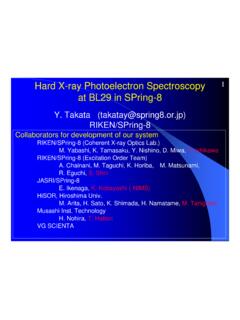
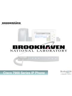
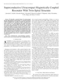
3 One ma- Fig. 1. The Nb3 Sn common coil at BNL with large empty space available for HTS insert coils (see left) and sketch (see right) schematically showing this jor purpose of this program was to perform magnetization studies empty space (31 mm wide and 338 mm high) between the Nb3 Sn coils. in the coils made with the HTS tape. Magnetization-induced field errors are expected to be small when the field is nearly parallel to the wide face of the tape. The magnetization measurements were TABLE I. performed at 77 K with the two racetrack coils in two orientations, MAJOR PARAMETERS OF THE LTS DIPOLE DCC017 FOR HTS INSERT COILS.
4 With field predominantly either parallel or perpendicular to the wide face of the HTS tape. In addition, measurements were also Dipole design 2-in-1 common coil performed at 4 K in different background fields provided by the Coil Technology Nb3 Sn React & Wind outer Nb3 Sn coils. This paper will summarize the magnetization Horizontal aperture (clear space) 31 mm measurements and present the quenching experience of the HTS Vertical aperture (clear space) 338 mm coils in this hybrid magnet system. Number of LTS coil layers Two Computed quench current kA. Index Terms Superconducting magnets, high field magnets, Peak field at quench current T.
5 Hybrid dipoles, HTS magnets. Computed quench field K T. Coil length (overall) 620 mm Coil straight section length 305 mm Coil inside radius in ends 70 mm I. INTRODUCTION Yoke length 653 mm NTEREST in HTS/LTS hybrid dipoles has risen recently I as a way to provide very high fields for future high energy colliders, such as the proposed Future Circular Collider (FCC) or program with the Department of Energy (DoE) grant to Particle High Energy upgrade to the Large Hadron Collider (HE-LHC) Beam Lasers, Inc. (PBL) and Brookhaven National Laboratory at CERN [1], [2] or the proposed Super proton-proton collider (BNL).
6 This was possible within the limited budget of the STTR. in China [3]. A hybrid dipole was assembled and tested recently due to an existing unique Nb3 Sn common coil dipole [4] that as a part of a Small Business Technology Transfer (STTR) has a large open space (see Fig. 1 and Table I) where the new HTS racetrack coils could be inserted without disassembling Manuscript received August 26, 2017; accepted December 21, 2017. Date of the magnet. The new HTS coils made direct contact with the publication January 5, 2018; date of current version January 15, 2018. This work existing LTS coils and became an integral part of the HTS/LTS.
7 Was supported in part by the Brookhaven Science Associates, LLC under Con- tract DE-SC0012704 and in part by the Department of Energy STTR. hybrid magnet structure. under Grant DE-SC0011348 to Particle Beam Lasers, Inc. (Corresponding II. MAGNET DESIGN. author: Ramesh Gupta.). R. Gupta, M. Anerella, J. Cozzolino, P. Joshi, W. Sampson, and P. Wanderer The program is based on the 2-in-1 common coil magnet are with Brookhaven National Laboratory, Upton, NY 11973 USA (e-mail: design [5], in which the simple racetrack coils are common J. Kolonko, D. Larson, R. Scanlan, R. Weggel, and E.)
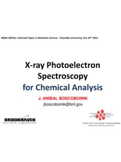
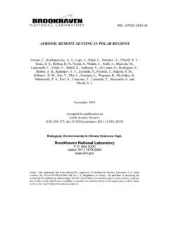
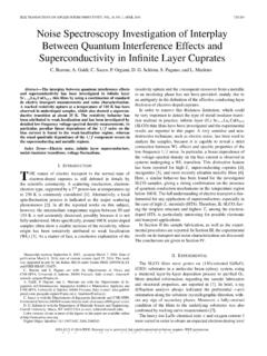
8 Willen are with Particle to two apertures with field of opposite polarity, as required in Beam Lasers, Inc., Northridge, CA 91324-2807 USA. collider magnets. Fig. 2 (left) shows the basic common coil Color versions of one or more of the figures in this paper are available online at concept with a pair of racetrack coils. Fig. 2 (right) shows a Digital Object Identifier magnetic model of the upper-half quadrant of the hybrid magnet 1051-8223 2018 ieee . Personal use is permitted, but republication/redistribution requires ieee permission. See standards/publications/ for more information.
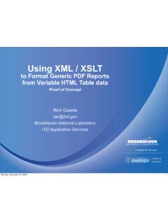
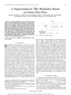
9 4002305 ieee TRANSACTIONS ON APPLIED SUPERCONDUCTIVITY , VOL. 28, NO. 3, APRIL 2018. Fig. 2. The basic concept of the common coil design (left) with a pair of racetrack coils producing field in opposite directions in two apertures, and the Fig. 4. Schematic design (left) of the hybrid magnet and the actual structure magnetic model of the upper-right quadrant (right) of the magnet tested. (right) with the new HTS coils inserted inside the LTS magnet. Fig. 3. Coil being wound with the universal coil winder with 4-ply ASC tape and Nomex insulation. A number of voltage-taps were also installed.
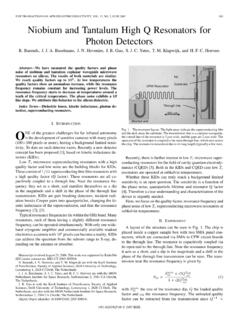
10 Fig. 5. Performance of hybrid dipole magnet as a function of the current in HTS coil under at the various fields generated by constant current in the Nb3 Sn coils. as built and tested. This magnet had two sets of Nb3 Sn coils, as shown in red, and one set of HTS coil, with the range of colors superimposed showing the magnitude of the field computed ( T to T) for 635 A in the HTS coils and 8000 A in the IV. HYBRID MAGNET TEST. Nb3 Sn coils. The iron yoke is shown in blue. A number of tests were performed at 4 K with only the HTS. coils powered, only the Nb3 Sn coils powered, and with the III.