Transcription of Immunity Testing to the CE Mark - Reverse …
1 1 of 7 112009 Immunity Testing for the CE Mark Summary The European Union (EU) currently has 25 member countries with 2 additional countries to be added in 2007. The total population at that time will be nearly a half billion people. In 2005, the total exports to the EU accounted for 20% of the total US exports. This number should continue to grow and should create more business for US exporters in years to come. Since January 1, 1996, manufacturers of electronic equipment have had to meet the Electromagnetic Compatibility (EMC) guidelines of EC Council Directive 89/336/EEC when shipping electrical and electronic products to the EU. Manufacturers must test and certify that their equipment meets the directive and they must apply a CE mark as testimony to this. Current and pending changes to the specifications that describe the tests to be made place more stringent requirements on the equipment used for CE mark Testing .
2 Indeed, future changes will require that the Testing equipment be able to expand its capabilities without causing the equipment to become useless. Introduction The legally prescribed test requirements for EMC standards in the EU are issued by CENELEC, the European Committee for Electrotechnical Standardization. CENELEC issues both Generic and Product standards. The generic standards are EN 61000-6-1, which addresses the requirements for Immunity Testing in the residential, commercial and light industrial environment. The industrial environment Immunity Testing required is addressed by EN61000-6-2. The generic standard for emission requirements in the residential, commercial and light industrial environment is covered in IEC 61000-6-3 and the industrial environment is addressed in EN 61000-6-4. The generic standards above apply to products for which no dedicated product or product-family standard exists.
3 If a product or product-family standard exists, it takes the place of the generic standards in prescribing the test requirements. The generic and product-family standards outline the test requirements. They refer to what is known as the Basic Standards to define the tests to be performed, the test methods, the test set-up and the specifications of the generator used to simulate interference phenomena. The International Electrotechnical Commisson (IEC) writes the basic standards to which CENELEC refers in their EN's. This article will focus on five of the European Standards from CENELEC used in the Immunity portion of the standards, four of which are required by the generic standards for CE mark certification. Basic Standards for EMC Immunity The IEC promotes standardization in the fields of electricity, electronics and related technologies. IEC 61000 part 3 covers emission specifications and IEC 61000 part 4 covers Immunity specifications.
4 The specifications are further broken down into sections. CENELEC has also adopted the same numbering system and refers to the specifications as EN's or European Norms. They are EN 61000-3 and EN 61000-4. The Immunity portions of the specifications are listed below in Table 1. 2 of 7 112009 Table 1: Basic Standards EN 61000-6-1 and EN 61000-6-2, Generic Immunity Standards refer to: EN 61000-4-2 IEC 61000-4-2 Electrostatic Discharge (ESD) EN 61000-4-3 IEC 61000-4-3 Radiated EM Field EN 61000-4-4 IEC 61000-4-4 Burst-Electrical Fast Transients (EFT) EN 61000-4-5 IEC 61000-4-5 Surge EN 61000-4-6 IEC 61000-4-6 Conducted Radio Frequency disturbances EN 61000-4-8 IEC 61000-4-8 Power frequency magnetic field EN 61000-4-9* IEC 61000-4-9* Pulse magnetic field EN 61000-4-11 IEC 61000-4-11 Voltage dips, interruptions *EN 61000-4-9 and IEC 61000-4-9 are not required by the Generic Standards but are referenced here for later use in this application note.
5 Interference Generation The Basic Standards also specify the generator to be used for simulating the interfering phenomena. But, since the disturbance phenomena have to be determined and measured first, the Basic Standards and the generator requirements usually lag behind the real environmental conditions. Consequently, the standards are subjected to constant changes. To reduce the cost of the generator used for Testing to the Immunity standards, it must be versatile and capable of covering as many of the foreseen specification changes as possible. Testing of one's own product is a requirement for the CE mark. This viewpoint is satisfactory; however, Immunity Testing of a manufactured product is also valuable as a tool to achieving customer satisfaction with the end product. If a product is not susceptible to ESD and fast transients for instance, it will not fail as readily during normal use.
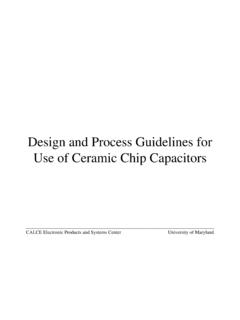
6 This is not only important from a performance standpoint, but from a safety and legal liability standpoint as well. Therefore, it is useful to use interference generators in the product design and development stage, as well as in the CE mark certification process. Burst The burst pulses, also called electrical fast transients (EFT), are created on public power lines by electrical arcs across switch contacts during opening of the switch. The nature of the loads connected to the power lines causes short bursts of pulses across the switch, which can generate interference in electrical/electronic equipment connected to the lines. Figure 1 shows the bursts called out by IEC 61000-4-4. The most recent version of the burst standard is IEC 61000-4-4:2004 Ed 2. The pulses within the 15-millisecond burst period are defined by the specification as having a frequency of 5 KHz.
7 The latest edition of the standard added 100 KHz as a new frequency and the burst duration for this pulse will be millisecond. The reduction in the burst duration is due to the energy content having to remain the same as the 5 KHz pulse. The burst pulses are applied in peak voltage levels from 500 volts to 4 KV on the power supply lines of the equipment under test (EUT). Because the burst pulses can be radiated into equipment signal lines (from nearby power leads), the burst pulses are also required to be capacitively coupled to the signal leads. 3 of 7 112009 SWITCH5/50 SPIKESPIKEV oltage acrossswitch on openingBURST GENERATION300ms15ms50ns5ns Figure1: Fast Transient/Burst Pulses The burst test is a low energy test, and as such, it is not destructive. The burst test is particularly hard on complex digital equipment with high clock frequencies. The test can cause degradation of performance, loss of function, uncontrolled process sequences, failures in programmable equipment, loss of information stored in memory and incorrect data processing.
8 For these reasons, the burst test should be the first test performed on an EUT. In order to take into account constantly increasing clock frequencies of microprocessor applications, higher burst pulse frequencies exceeding the 5 KHz specified frequency and even higher than the 100 KHz proposed frequency should be used in developmental Testing . If the burst Testing were done at 5 KHz, it would take many tests to find and isolate a burst susceptibility design problem. If, for example, the EUT were to have a clock frequency of 10 MHz, the 5 KHz burst pulse tests only every 2,000th function state. The test piece's critical states are likely to be among the 1,999 function states not tested. If the Testing is done at 100 KHz, the design problems can be more quickly discovered because 20 times as many function states are tested in any given Testing time. CENELEC has also added new requirements related to pulse verification and calibration of the burst generator.
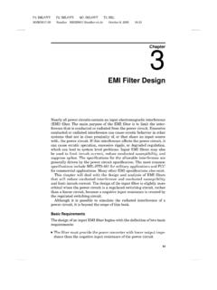
9 These are included in Ed 2 of the IEC 61000-4-4 standard. According to Amendment A2:2001 to the IEC 61000-4-4:1995 standard, test generators must meet the verification and calibration requirements effective July 1, 2004. The changes made require that the burst pulse be verified at the generator coaxial output into an open circuit (1000 ohms) and into a 50-ohm load. Newly added to the Ed 2 standard, the burst verification also needs to be performed at the generator coupling/decoupling output with a 50 ohm load. Because of the high frequency character of the burst pulses, to reduce stray capacitance, a special coaxial adapter (see Figure 2 below) and a minimum 400 MHz bandwidth oscilloscope is required to make the pulse verification. The specification changes were made to achieve 4 of 7 112009 more uniform pulse characteristics among the various transient generator manufacturers and to provide repeatable test results.
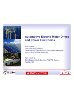
10 Figure 2: Coaxial Adapater for Burst Pulse Observation Since the burst test is relatively easy to set up and its reproducibility is high, the test is suitable for in-house developmental Testing . Surge IEC 61000-4-5 prescribes tests for simulating the effects of lightning discharges as well as voltage surges caused by switching disturbances in power stations. The surge waveforms are defined by the specification as shown in Figures 3 and 4 below. The peak voltage for the voltage waveform in Figure 3 varies between 500V and The peak current in Figure 4 is between 250A and Figure 3: Waveform of Open Circuit Voltage ( s) 5 of 7 112009 Figure 4: Waveform of Short Circuit Current (8/20 s) IEC 61000-4-5 requires that the generator be capable of applying surge pulses at a rate of "at least one per minute". The surge pulse must be applied at 0, 90, 180, and 270 degrees of the power input waveform.