Transcription of Improving Brushless DC Motor Control for Better …
1 Improving Brushless DC Motor Control for Better efficiency and performance in industrial , White and Brown GoodsTechnology BackgrounderImproving BLDC Motor Control for Better efficiency and performance in industrial , White and Brown GoodsPage 1 fujitsu Microelectronics America, compete in a market increasingly driven by efficiency concerns, vendors of industrial machines and household appliances must make best use of high- efficiency Brushless DC (BLDC) motors. Today s microcontrollers offer the compute power and specialized features needed to leverage BLDC motors while minimizing implementation costs. The most useful microcontroller features are specialized timers and on-chip CPU accelerators that eliminate the need for an external digital signal processor (DSP) even in sensorless Control advantage of these features with BLDC motors helps meet government regulations for power efficiency and qualify for ratings (such as Energy Star) that boost sales.
2 BLDC motors are ideal for meeting these goals with a number of physical and electrical advantages: By eliminating brushes, BLDC motors last longer and run quieter than comparable previous-generation brushed DC motors. BLDC motors can deliver higher torque than their brushed counterparts. In addition to being more reliable, quieter, and stronger, BLDC motors can run faster than brushed DC motors. BLDC motors can be sealed ( for dishwasher pumps) or even run directly in to these characteristics, BLDC motors market share has been growing significantly in automotive and industrial applications. The latter include electric vehicles, low-end and medium-range industrial drives, office automation equipment, HVAC actuators and fans, vending and cash machines.
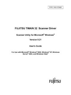
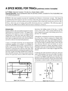
3 Many hard disk drives use a BLDC Motor to turn the spindle. In the home, BLDC motors are used in washing machines, dishwashers, refrigerators and air Motor Control Controlling a BLDC Motor requires information about the rotor position and speed. Getting this information from three Hall sensors (or encoders) on the Motor shaft is straightforward. Each Hall sensor outputs a high level for 180 of an electrical rotation, and a low level for the other 180 . The three sensors have a 60 relative offset from each other. This arrangement divides a rotation into six phases (3-bit code). The microcontroller reads the 3-bit code and determines the position of the rotor (Figure 1).
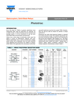
4 Commutation in the right direction is calculated by reading consecutive Hall sensor positions. Though Hall sensors simplify BLDC Motor Control , they add cost as well as extra wires to the Motor that are susceptible to corrosion and can act as a source of EMI. Hence, many applications are moving away from sensor-based Control . The most popular sensorless method for detecting rotor position is to measure the back-EMF in the non-conducting phase of the BLDC Motor winding. Using this measurement to calculate the zero crossing of each phase is CPU intensive and thus requires a higher- performance microcontroller than is needed for the sensor-based method. However, the necessary performance is readily available from today s microcontrollers and is widely useful in products for Improving overall efficiency and implementing product features such as a sophisticated user interface.
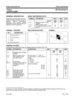
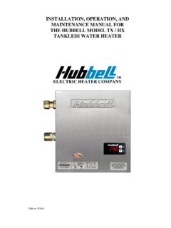
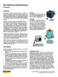
5 Along with higher compute power, the microcontroller needs to provide a versatile timer, referred as a multifunctional timer in fujitsu microcontrollers. As mentioned earlier, an arithmetic accelerator also proves to be quite useful. The rest of this paper looks at these and other microcontroller features that are useful for implementing the BLDC Motor Control algorithm outlined in Figure 2 on the following AdjustHall Sensor InterruptSpace VectorPWM (SVPWM) MotorMotor SpeedRotor PositionHall Sensor SignalsMotor DrivingSignalVoltage ControlFigure 1 Hall-sensor-based BLDC Motor Control algorithmImproving BLDC Motor Control for Better efficiency and Performnce in industrial , White and Brown GoodsPage 2 fujitsu Microelectronics America, timerThe multifunction timer (MFT) in a fujitsu microcontroller includes a timer, input capture, output compare, a programmable pulse generator (PPG)
6 , and a waveform generator (Figure 3). These features are used for controlling BLDC motors as follows: Free-running timer Using an up/up-down counter and Control registers, this timer generates the pulse-width modulation (PWM) switching frequency for the isolated-gate bipolar transistors (IGBTs) that actually drive power to the Motor . Output compare unit This unit determines the duty cycle of each PWM cycle using compare registers, compare output latch, and compare Control registers. An interrupt is generated when the values of the free-running timer and the compare register match. Input capture This function consists of four independent external input pins that feed capture registers and capture Control registers.
7 When the function detects an edge of the input signal from the external pin, the value of the free-running timer is stored in the capture register and an interrupt is generated simultaneously. When using the sensor-based BLDC Control method, input capture can be used for reading the Hall sensor input or encoder input. Waveform generator This unit outputs PWM signals to drive six IGBT inverter power switches. The waveform generator provides a dead-time timer, which generates the non-overlap signal required to ensure that the positive and negative drive transistors never turn on simultaneously. Axial TransformPI AdjustA/DSampleSliding ModeObserver (SMO)Space VectorPWM (SVPWM)
8 D-q AxialCurrent SensorRotorPositionMotor DrivingSignalVoltage ControlMotorFigure 2 Sensorless BLDC Motor Control algorithmF2MC / FR BusReal time I/O16-bit OutputCompare16-bit Free-Running TimerWaveformGenerator16-bit InputCaptureInterrupt #12 output compare 0 Interrupt #15 output compare 1 Interrupt #17 output compare 2 Interrupt #19 output compare 3 Interrupt #21 output compare 4 Interrupt #23 output compare 5 Interrupt #31 Zero defectRT05 RT05 Interrupt #33 Input capture 0/1 Counter valueIN0IN1IN2IN3A/D trigger A/D triggerEXCK buffer transfer counter valueRTO0 P30/RTO0 (U)RTO1 P31/RTO1 (X)RTO2 P32/RTO2 (V)RTO3 P33/RT03 (Y)RT04 P34/RT04 (W)RT05 P35/RTO5 (Z)
9 DTTI P10/INTT0/DTTI0 Interrupt #34 Compare clearInterrupt #35 Input capture 2/3 PinPinPinPinPinPinPinPinInterrup #29 16-bit timer 0/1/2 underflowInterrupt #20 DTTI0 failing edge detect PPG0 PPG0 GATE GATEP17/FRCKPinP24/IN0 PinP25/IN1 PinP26/IN2 PinP27/IN3 Figure 3 Multifunctional timerImproving BLDC Motor Control for Better efficiency and performance in industrial , White and Brown GoodsPage 3 fujitsu Microelectronics America, design using multifunction timerA washing machine serves as a good example of a product that usually employs a three-phase BLDC Motor that is controlled using the Hall sensor method or sensorless Control (Figure 4).
10 Both of these methods require use of specialized timers synchronized with other microcontroller peripherals such as A/D converters (ADCs) and a fail-safe unit. The multifunction timer integrates all the necessary analog and digital functionality for the washing machine. The free-running timer can generate a wide range of carrier frequencies for creating the PWM waveform for Motor Control , while the MFT s analog interface handles the Control tasks associated with Hall sensors or sensorless measurements. The analog functions include two independent, high-speed, 12-bit ADC (A/D converters) units (conversion time: s) with a dedicated result register for every ADC channel. The ADC measurements are precisely synchronized to the PWM switching events, minimizing noise and allowing two ADC samples to be taken at the same time.