Transcription of Installation and Maintenance3Instructions for …
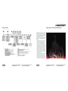
1 Installation and Maintenance Instructions for B400 & b700 ASHCROFT Snap Action Switches for Pressure ControlINTRODUCTIONThe Ashcroft pressure switch is a precision built agencyapproved control device which features a mechanical snapaction switch. Controllers are available for operation on pres-sure or vacuum with fixed or variable differential. Also manualreset types for operation on increasing or decreasing manual reset types remain tripped until reset by pressing abutton on top of the enclosure. Standard electrical switch isSPDT, available with various electrical characteristics. TwoSPDT switch elements mounted together are available excepton variable Deadband and manual reset types. Various wettedmaterial constructions for compatibility with a range of pressuremedia may be Ashcroft snap action pressure switch is furnished in thestandard NEMA 4 and explosion-proof NEMA 7 & 9 enclosurestyles.
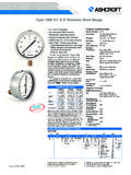
2 Both enclosures are epoxy coated aluminum controls are precision instruments and should never beleft with internal components exposed. During Installation insurethat covers are in place and conduit openings are closed exceptwhen actually working on the B400 AND b700 SERIEST hree holes external to the enclosure for surface of these holes is shown on the general dimension draw-ing. They may also be mounted directly on pressure line usingthe pressure connection. When tightening control to pressureline, always use the wrench flats or hex on the lower CONNECTIONSR emove coverB400 Series two screws hold cover to enclosureB700 Series cover unscrewsCONDUIT CONNECTIONSNote It is recommended that Teflon tape or other sealant beused on conduit, bushing or plug threads to ensure integrity ofthe DIMENSIONSB700 lb(.81 kg) lb( kg) lb( kg)STANDARD RANGES15, 30, 60, 100, 200, 400, 600 psi1000, 3000 psi30 Hg RANGES10, 30, 60, 100, 150 H2O15 H2O H2O 2015 Ashcroft Inc.
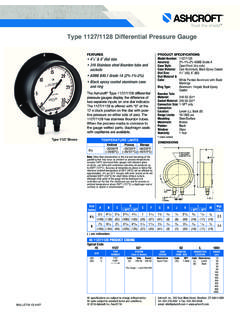
3 , 250 East Main Street, Stratford, CT 06614-5145, USA, Tel: 203-378-8281, Fax: 203-385-0499, sales subject to standard terms and conditions of sale. I&M009-10008-10/00 (250-2246E) 06 . HOLES1/4 NPTFEMALE . HOLES . NPTFEMALE1/4 NPTFEMALEBRACKET WHEN"XBP" (132) (92) (55) (8) (111) (35) x 3 HOLES(7) (28) (130) (49) (71) (89) (9) (35) (13) (9) X 2 HOLES(9) (99) (1) (91) (8) (143) (78) (31)1/4 NPT FEMALE3/4 NPT2 HOLESBRACKET WHEN REQUIRED "XBP" (49) (132) (92) (55) (8) (111) (35) (146) x 3 HOLES(7) (99) (1) (91) (59) (8) (31)1/4 NPT FEMALE3/4 NPT 2 HOLESB400 Series standard one 3 4 NPT conduit hole right Series standard two 3 4 N PT conduit holes with onepermanent plug. NEMA 7 & 9 enclosures require proper conduitseals and breathers as per the National Electrical & b700 Series XJL variation two 3 4 NPT conduitholes with two 3 4 to 1 2 NPT reducing Series XJK variation two 3 4 NPT conduit SERIESSPDT Wire directly to the switch according to circuit require-ments.
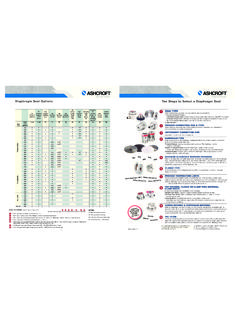
4 On controls with pilot lights wire lights according to cir-cuit diagram on inside of cover. See special wiring instructiontag for single switches with two pilot lights and dual switcheswith one or more SPDT Dual switching elements consist of two SPDT switch-es mounted together in a bracket. Switches are calibrated tohave simultaneous operation within 1% of range either onincreasing or decreasing pressure but not in both directly to the front and rear switch according to circuitrequirements. Leads are provided on rear switch color coded asfollows:Common WhiteNormally Closed RedNormally Open BlueSee SPDT instructions for pilot light hermetically sealed switch elements(s) are supplied, thelead color coding is as follows:Common WhiteNormally Closed RedNormally Open BlueB700 SERIESSPDT Wire directly to the switch according to circuit SPDT Wire to front switch terminal block (left) and rearswitch terminal block (right) as marked.
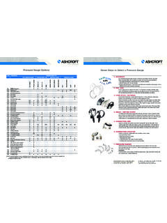
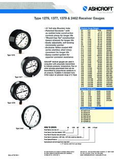
5 Strip insulation 5 16 ,insert in proper terminal connector and tighten clamping screwto OF SETPOINTB400 & b700 Series A single setpoint adjustment nut (7 8 ) islocated centrally at the bottom on the inside of the accurate setpoint calibration, mount the switch on a cali-bration stand, a pump or catalog deadweight gaugetester. A suitable reference standard such as an AshcroftDuragauge or Test Gauge is necessary to observe convenientchanges in received, the pressure switch will normally be set toapproximately 90% of the indicated range. Pressurize the system to required setpoint and turn the adjustment nut untilswitch changes mode. Direction of turning is indicated on alabel affixed to the inside of the control enclosure. When set-point has been achieved raise and lower pressure to insure thatsetpoint is LOCKING SCREW (B400 ONLY)Once setpoint has been determined, tighten setpoint lockingscrew using a 5/64 allen (hex) wrench.
6 Do not over torque; setpoint locking screw only needs to be hand performing calibration or changing the setpoint, the setpointlocking screw should be loosened before turning the setpointadjusting nut. Once calibration is complete, re-tighten the set-point locking Installation of the control replace cover to insure electricalsafety and to protect internal parts from the and B750 VARIABLE DEADBAND SWITCHESD eadband is varied by rotating the wheel on the precisionswitch. When viewed from the front of the enclosure, rotation tothe left increases deadband rotation to the right decreasesdeadband. Letters on the wheel may be used as a obtainable will vary from to 9% of pressurerange depending on range segment and type of OF SETPOINTAs received, the pressure switch will normally be set to approxi-mately 90% of range. Rotate the wheel on the MICRO SWITCHall the way to the right; this will provide smallest the system to the required setpoint and turn theadjustment nut until the switch changes mode.
7 Lower the pressure to reset the switch. Rotate the wheel on the MICROSWITCH until the desired deadband is obtained. The upper setpoint will be changing upward with this adjustment. Lowerthe pressure to reset the switch. Then increase the pressure tothe desired setpoint and turn the adjusting nut until the switchchanges mode. Lower the pressure and check resetpoint anddeadband. Note As indicated above, adjustment of setpoint is made byuse of 7 8 nut. Precision switch element mountingscrews and bracket adjusting screw are factory sealedand should not be tampered Since vacuum models are already above setpoint atatmosphere, the Normally Open (NO) circuit will beclosed as PracticesAshcroft recommends regular inspection of the operation andsetpoint of the switch in critical applications to prevent issuesthat could cause severe damage to personnel or and Maintenance Instructions for B400 & b700 ASHCROFT Snap Action Switches for Pressure ControlTERMINAL BLOCKSWITCH ATERMINAL BLOCKSWITCH B213213 NCNOCNCNOC 2015 Ashcroft Inc.
8 , 250 East Main Street, Stratford, CT 06614-5145, USA, Tel: 203-378-8281, Fax: 203-385-0499, sales subject to standard terms and conditions of sale. I&M009-10008-10/00 (250-2246E) 06/15 SetpointLockingScrew