Transcription of INSTALLATION AND OPERATING INSTRUCTIONS
1 GENERAL INFORMATIONThis wall control is designed to separately control your ceiling fan speed and light brightness. There are four buttons (Hi, Med, Low, Off) to control the fan speed. The light dimmer button controls the ON/OFF switch is to turn the power to wall control On or Off. The red indicator on the transmitter will light when any button is AND OPERATING INSTRUCTIONSNOTE: Before installing this unit, change the factory code switch setting to your preferred setting. Be sure the code switch positions on the transmitter and receiver match each other or the ceiling fan will not function. If this unit causes interference with other appliances, you may need to select different : Not compatible for use with compact fluorescent bulb(s).I. SETTING THE CODEThis unit has 16 different code combinations.
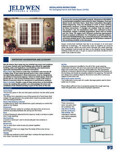
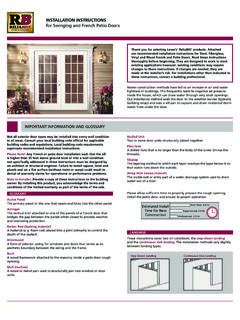
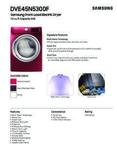
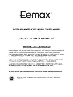
2 To set the code, perform these steps: A. Setting the code on the transmitter:1. Slide code switches to your choice of up or down position. (Factory settingis all up). Do not use this position. Use a small screwdriver or ballpoint pento slide firmly up or down (Figure 1). B. Setting the code on the receiver:1. Slide code switches to the same positions as set on your transmitter (Figure 2).II. INSTALLING RECEIVER IN ceiling FAN (Please refer to Figure 3 before continuing.) A. Safety precautions:WARNING: HIGH VOLTAGE! Household electrical power can cause serious injury or death. Disconnect source of electrical power to the ceiling fan by removing fuse or switching off circuit breaker. Make sure all electrical connections comply with local codes or ordinances and the National Electrical Code.
3 If you are unfamiliar with electrical wiring, please use a qualified and licensed : To reduce the risk of fire, electrical shock, or personal injury, wire connectors provided with the wall control receiver are designed to accept only one 12 gauge house wire and no more than two lead wires from the receiver. If your house wire is larger than 12 gauge or there is more than one house wire to connect to the two receiver wires, consult an electrician for the proper size wire connectors to : TO REDUCE THE RISK OF FIRE OR INJURY, DO NOT USE THIS PRODUCTIN CONJUNCTION WITH ANY V ARIABLE (RHEOSTAT) WALL not use with solid state ceiling source and fan must be 115/120 volts, 60 Hz. Maximum fan motor amps: and maximum light watts: 300 incandescent only. B. Installing receiver in fan:1.
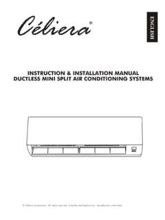
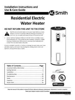
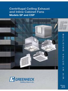
4 Remove ceiling fan canopy from the mounting Disconnect existing wiring between ceiling fan and supply atelectrical junction Lay the black antenna wire on top of the receiver, and slide thereceiver in the mounting bracket (Figure 3).4. Make wiring connections as follows, using the wire connectors supplied (Figure 4):CONNECT TO GREEN fan supply wire BLACK receiver wire (AC IN L)..BLACK supply wire WHITE receiver wire (AC IN N)..WHITE supply wire WHITE receiver wire (TO MOTOR N)..WHITE fan wire BLACK receiver wire (TO MOTOR L)..BLACK fan wire BLUE receiver wire (FOR LIGHT)..BLUE light wire If other fan or supply wires are different color, have this unit installed by a qualified Push all connected wires up into junction Reinstall the canopy on the mounting bracket.
5 7. Restore electrical power. C. Manually set fan speed control to HIGH via pull chain and set light to ON via pull chain. IMPORTANT: Fan speed and light control will not be activated by remote if pull chains for fan and light are not set to the HIGH and ON positions, INSTALLING WALL CONTROL (TRANSMITTER): Remove wall plate, disconnect and remove the toggle switch from wall switch box. Using the wire connectors provided, make the electrical connections to the wall control (transmitter) unit as shown in Figure 4. Carefully push all connected wires back inside wall switch box. Secure wall control (transmitter) with 2 screws provided. Attach wall plate cover with the 2 original screws. IV . OPERATING TRANSMITTER: A. This remote control unit is equipped with 16 code combinations to prevent possible interference from or to other remote units such as garage door openers, car alarms or security systems.
6 If you find that your fan and light kit go on and off without using your remote control, simply change the combination code in your transmitter and receiver. B. Operation buttons on the panel of the transmitter: HI button for fan high speed MED button for fan medium speed LOW button for fan low speed OFF button for fan speed off LIGHT button for light brightness and off The light function is controlled by pressing the LIGHT button. Hold button down to increase or decrease light. Tap button quickly toturn light off or on. If you press the button in excess of second it becomes a dimmer. The light varies cyclically in light button has auto resume, so the light will stay at the same brightness as the last time it was turned : Turn fan off at wall switch and let blades come to a complete stop before manually activating the reverse REMOTE CONTROL NOW HAS FULL CONTROL OF THE FAN AND TROUBLESHOOTING GUIDE NOTICE!
7 A. Fails to operate: Your ceiling fan and light kit assembly must meet 1. Power to the receiver? the following requirements: 2. Receiver wired correctly? 1. Do not use with solid state fans . 3. Fan manual speed control in highest position? 2. Electrical rating: 120V / 60 Hz, 4. Light kit switch turned on? MAX. motor amps: 5. Good battery in the transmitter? MAX. light watts: 300 6. Code set at exact same position in both transmitter and receiver? (Incandescent only) B. Won't operate at distance: If transmitter operates fan and light kit when up close, but not at 40 feet away, try placing the black antenna wire higher and make sure the black antenna wire is visible. 1234 WALL CONTROLFig.
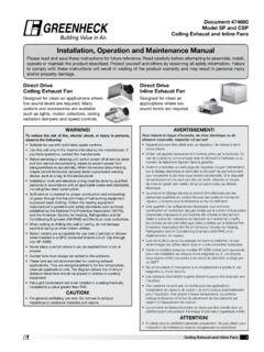
8 1 RECEIVERFig. 2 CODE SWITCHESFig. 4 Fig. 325 26 and AboveAC 120V SUPPLYBLACKWHITEBAREGREENGREENWHITEWHITE BLUEBLUEBLACKBLACKBLACKBLACKBLACKBLACKAN TENNARECEIVERBRACKETDOWNROD MODEL: WC-100 LCAUTION: ceiling ANGLE SHALL NOT EXCEED 25 DEGREES FOR MOUNTING RECEIVER, MODELS: UC7067 OR UC7068, UC7067 RCWALL CONTROLLITEX INDUSTRIES, PRAIRIE, TX 75050 For Customer Service call:1-800-527-1292 Fig. 5 RECEIVER CAUTION: DO NOT USE FAN SPEED CONTROL IN CANOPIES WHERE THE MOUNTING IS NOT AS DESCRIBED IN FIGURE 5 OF THE INSTALLATION INSTRUCTIONSCAUTION: TO REDUCE THE RISK OF FIRE OR INJURY, DO NOT USE THIS PRODUCT IN CONJUNCTION WITH ANY V ARIABLE (RHEOSTAT) WALL CONTROL.