Transcription of Installation Guide - Cisco
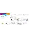
1 Cisco TelePresence SpeakerTrack 60 Installation GUIDEThe SpeakerTrack 60 uses a unique dual-camera technique to quickly view a close-up of the active speaker in the meeting | OCTOBER 2016. Copyright 2016 Cisco Systems, Inc. All rights invite you to explore the Project Workplace Guide to inspire you on room design and room setup. Go to: box contentsA. 1 Cover plateB. 1 Microphone panel with four biult-in microphonesC. 2 Precision 60 CameraD. 1 Base unit, with connectors1 Accessories box1 Installation GuideAccessoriesE. 2 Camera interface plateF. 1 Wall bracketG. 1 DC Power cable w/ barrel plug, 20 cm / inH. 1 DC Power cable w/ barrel plug, 45 cm / inI. 1 Ethernet cable, 20 cm / inJ. 1 Ethernet cable, 35 cm / inK. 1 Power adapter and power cableL. 1 GlovesM. 1 Torx Key (T20)N. 1 Allen KeyO. 2 Thumb nut, M4P. 4 Pan headed screw, M4 16 mmQ. 2 1/4 UNC screwR. 1 Template for attaching the wall bracket (not shown)BDFEGIHJCAKLNMOQPWARNING: Use Ethernet cable only when connecting to the Ethernet port on the camera.
2 Do not connect a serial VISCA cable to the Ethernet port on the camera, as this will cause severe damage to the instructionsNOTE It is of great importance that the wall mount unit is safely installed, that the wall is able to support the product and that the screws or mounting means used are suitable for the wall and the weight of the product. This type of equipment is to be installed by the submitter s/dealer s qualified installer. The installer is responsible for obtaining safety inspection of the structural integrity of the Installation by the local authority/inspection department. Note that the surface is hot when the camera is in field of viewThe participants should be seated within the horizontal field of view. Participants seated outside the horizontal field of view will not have optimal audio field of view 80 Microphone rangeThe participants should be seated within the maximum microphone range. For optimal audio tracking the SpeakerTrack 60 should be mounted at some distance from the side microphone range 900 cm / 354 inMinimum distance to the side walls 120 cm / in Mounting height not above 183 cm / 72 inSpeakerTrack 60 mounted above the monitor Mounting height not below 107 cm / 42 inSpeakerTrack 60 mounted below the monitorOption 1: Mount the camera on the wallThe SpeakerTrack 60 can be mounted above or below the monitor.
3 For large monitors (70 and above), we recommend mounting the SpeakerTrack 60 below the monitor. Select a mounting height for SpeakerTrack 60 that provides clear line of sight, to all four edges of the microphone panel, from all appropriate positions in the meeting room. NOTE: Obstacles placed in front of the microphone panel, or in the sight line of the microphones, will cause severe loss in the speaker track distance to the ceiling 40 cm / inOption 2: Mount the camera in a recessThe recommendations for mounting the camera in a recess are the same as for mounting it on the wall, with the following addition: If mounted in a recess, the sound from any participant in the room must reach at least three of the four microphones on the microphone panel. To achieve this, the recess should have slanted walls*. SpeakerTrack 60 mounted in a recess above the monitor The bottom wall of the recess is slanted 17 The side walls of the recess are slanted 45 The maximum depth of the recess is 218 mm ( in).
4 If less the camera will protrude from the wall. Follow local building regulations and accessibility requirements. 82 cm ( in)32 cm ( in)SpeakerTrack 60 mounted in a recess below the monitor82 cm ( in)32 cm ( in) The upper wall of the recess is slanted 17 The side walls of the recess are slanted 45 The maximum depth of the recess is 218 mm ( in). If less the camera will protrude from the wall. Follow local building regulations and accessibility requirements. * CAD drawings with details and dimensions: and navigate to: Collaboration Endpoints > Collaboration Peripherals > TelePresence Peripherals > TelePresence SpeakerTrack 60 > Technical ReferencesMount the wall bracketNOTE: Read the mounting guidelines and safety instructions before you start mounting the wall bracket (F). Use the Template for attaching the wall bracket (R), found with the accessories, and follow the instructions on the template when mounting the wall | FEBRUARY 2014. Copyright 2014 Cisco Systems, Inc.
5 All rights | FEBRUARY 2014. Copyright 2014 Cisco Systems, Inc. All rights for attaching wall bracket for SpeakerTrack 60 Gabarit de fixation du support mural pour SpeakerTrack 60 Check that the unit is level. V rifiez que l appareil est 60 rear panelSpeakerTrack 60 panneau arri reThe monitor center pointTemplate for drilling holes (found overleaf)Mod le pour les trous de forage (qui se trouve au verso)Wall bracketSupport muralFind the center point of the monitor and the top center point of the SpeakerTrack 60 rear panel. Localisez le centre du moniteur et le centre sup rieur du SpeakerTrack 60. Use the template on the other side of this sheet when drilling holes for the wall bracket. Screw dimension le mod le au verso de cette page pour le per age des trous de la fixation murale. Vis dimension the type of attachment for the wall bracket on the basis of the type of material the wall is made of (wood, concrete, gypsum).S lectionnez le type de fixation du support mural en fonction du type de mat riau du mur (bois, ciment, gypse).
6 Template Page 1 Template Page 2 Mount the base unitPlace the microphone panel (B) on a clean and stable surface (for example a table) with the microphone cables headed up and the textile headed down. Remove the cover plate (A) from the base unit before this operation. Hold the base unit (D) as illustrated and slide in place. Make sure the Guide -pins positions the four pan headed screws (P) when fastening the base unit. Use the Torx Key (M) and tighten the the supplied gloves (L).Mount the cablesConnect the cables to the connector panel on the base unit: 1. Find the Ethernet cables (I, J) and the power cables (G, H) in the accessories box. Connect the short cables to the connectors marked R () and the long cables to the connectors marked L (). Lead them through the open slot to make them available for camera mounting. 2. Connect the microphone cables coming from the microphone panel. 3. Find the power adapter and the power cable (K) in the accessories box. Connect the power cable to the base Connect an Ethernet cable (not included) to the Ethernet port on the base unit.
7 Connect the other end directly to the codec. If you do not have any free Ethernet port on the codec (typically if a Touch device is connected) you will need a network switch. Connect the switch to the Ethernet port on the codec, and connect the Touch device and SpeakerTrack 60 to the switch. We recommend using a Cisco viewConnect the short Ethernet and power cables to the right camera, and the long Ethernet and power cables to the left the microphone cables that comes from the microphone the power the Ethernet cable (not included) directly to the codec (Eth2/Eth3).Mount the interface plate to the camerasPlace the camera (C) on a stable surface as illustrated. Use the 1/4 UNC screw (Q) and Allen Key (N) and mount the camera interface plate (E) to the camera. Repeat these steps for the second camera (C).Mount the assembly to the wallHold and lift the unit as illustrated. Carefully place the unit onto the wall bracket. Check that the unit is level. If not, you can adjust the unit the camera cablesIt can be a bit cramped when you connect and secure the cameras, so you ll probably want to inspect the camera connector panel to know where the HDMI, Ethernet and power are with the camera to the right and hold the camera as illustrated.
8 Make sure the short cables (Ethernet and power) are available for this camera and connect the cables. Then connect the HDMI cable coming from the codec. Guide the camera into position. Proceed with the camera to the left and hold the camera the same way as you did with the first camera. Connect the long cables (Ethernet and power) to the left camera. Connect the HDMI cable coming from the codec. Guide the camera into ,0 AConnect one HDMI cable to each camera. The HDMI cables for the two cameras are going to the codec. The Ethernet and power cables are coming from the base unit. The short cables goes to the right camera and the longer cables to the left sideLeft sideFasten the camerasMake sure the pins on the base plate fits the holes in the camera interface the thumb nut (O) to attach the camera to the base. Repeat this step for the second sure the pins on the base plate fits the holes in the camera interface documentation and supportUser documentation for SpeakerTrack 60: to: Collaboration Endpoints > Collaboration Peripherals > TelePresence Peripherals > TelePresence SpeakerTrack 60 For support, go to: up Move the two cameras into standby position as illustrated and carefully slide the cover plate (A) on place.
9 Use a cable management for a good aesthetic appearance. Connect the Ethernet and HDMI cables to the codec, see the codec documentation for further information. Connect the power cable to the power left cameraEthernetPowerHDMI right cameraFor a list of offices, visit the Cisco website at and the Cisco logo are trademarks or registered trademarks of Cisco and/or its affiliates in the and other countries. To view a list of Cisco trademarks, go to this URL: Third-party trademarks mentioned are the property of their respective owners. The use of the word partner does not imply a partnership relationship between Cisco and any other company. (1110R)