Transcription of Installation Installation Instructions Built-in Trim Kit ...
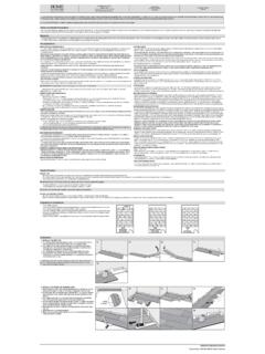
1 Installation Instructions Installation Built-in trim Kit Instructions Model # MWTK27 FGUF MWTK30 FGUD MWTK30 FPUF. MWTK30 FGUF MWTK27 FGUD. BEFORE YOU BEGIN Read these Instructions completely and carefully. IMPORTANT Save these Instructions Proper Installation is the responsibility of the for local inspector's use. installer. Product failure due to improper Installation is IMPORTANT Observe all governing not covered under the Warranty. codes and ordinaces. Unplug the microwave oven before Note to Installer Be sure to leave attempting Installation of this kit.
2 These Instructions with the Consumer. Because the kit includes metal parts, caution Note to Consumer Keep these should be used in handling and Installation to avoid the possibility of injury. Instructions for future reference. Do not remove permanently affixed labels, Skill level - Installation of this appliance warnings, or plates from the product. This requires basic mechanical and electrical may void the warranty. skills. IMPORTANT - PLEASE READ. FOR YOUR SAFETY: AND FOLLOW. WARNING Before beginning the Installation , switch power off at service panel and lock out THIS Built-in KIT IS DESIGNED FOR USE.
3 To prevent being switched on accidentally. ONLY WITH ELECTROLUX microwave . When the service cannot be locked, securely fasten ovens SPECIFYING Built-in KIT. a prominent warning device, such as a tag, to the service panel. QUESTIONS? For customers in the United States call:1-800-944-9044. For customers in Canada call: 1-800-265-8352 (English). 1-800-668-4606 (French). Visit our Website at: READ CAREFULLY. KEEP THESE Instructions . PN: A06823511. June 2018. EN-1. Installation Instructions PARTS INCLUDED IN THE KIT. 1. Front Frame Assembly- QTY 1.
4 2. Exhaust Duct - QTY 1. Bottom Mounting Rail QTY 2. 3. Screw A - QTY 11+ 3 extra Screw A. 4. Screw B - QTY 4 + 2 extra CHOOSING A LOCATION FOR. Screw B. YOUR microwave OVEN IF Front Frame Assembly Built-in . Built-in trim Kit allows for the Installation of microwaves listed below to be built into a cabinet or wall by itself or over an electric wall oven*. microwave Models: FGMO226 NUF FGMO226 NUD FPMO227 NUF. CGMO226 NUF CPMO227 NUF. Exhaust Duct Bottom Mounting Rail See Illustration 1 for proper location and when building in above a wall oven.
5 Carefully follow both the wall oven Illustration 1. Installation Instructions and Electrolux's Built-in Kit Instructions . If building over a wall oven, be sure the clearance between the wall oven and the microwave oven is a minimum of 3 illustration 2. *NOTE: trim Kit and microwave can only be Built-in over an electric self-clean or non self-clean single cavity wall oven. 3"Min CABINET OR WALL CUTOUT. Cutout Dimensions( See illustration 3). Height (A). Minimum 16 3/4 " ( cm). Maximum 17 " ( cm). Width (B). Illustration 2.
6 Minimum 24 3/4 " ( cm). Maximum 25" ( cm). Depth (C) trim Kit Overall Dimensions Minimum 20" ( cm) MWTK27 MWTK30. Height 18" 458mm 18" 458mm . Width 27" 686mm 30" 762mm . Depth 1 1/2" ( ) 1 1/2" ( ). EN-2. Installation Instructions Screw A. Center Line Illustration 3. Illustration 4. ELECTRICAL OUTLET LOCATION EXHAUST DUCT ASSEMBLY. Outlet should NOT be in the shaded area as indicated 1. Draw a Central Line on floor. Place the Exhaust on Illustration 3 Duct in the opening When the Exhaust Duct Assembly is in the opening correctly, the Center NOTE 1: Line is in the middle of the Exhaust Duct The floor of the opening should be constructed of Assembly.
7 See Illustration 4. plywood strong enough to support the weight of the 2. Secure the Exhaust Duct Assembly with the oven and floor load (approximately 100 pounds). The three screws A. floor should be level for proper operation of the oven. Be sure to check the local building code as it may require IMPORTANT: Secure screws in outer hole. that the opening be enclosed with side, ceiling and rear 3 pcs are needed for exhaust duct assembly partition. The proper functioning of the oven does not require the enclosure. EN-3.
8 Installation Instructions Bottom Mounting Rail OVEN Installation . Turn microwave upside down so you are 1. Place the oven adjacent to the wall or cabinet looking at oven bottom. Secure the bottom opening. Plug the power cord into the electrical Mounting Rail on oven with four SCREWS A. outlet. See Illustration 5. 2. Carefully guide the assembled oven into the prepared opening. Slide the oven on the NOTE: Please make sure to align the holes(marked with 36 ) Exhaust Duct Assembly. See Illustration 6. of bottom mounting rail and the holes(marked with 36 ) 3.
9 Secure the Exhaust Duct Assembly with the four of microwave oven's bottom plate. screws A. Screw A. Guide line Guide line Screw A. Illustration 5 Illustration 6. EN-4. Installation Instructions FRAME Installation . 1. Position the FRAME ASSEMBLY to be square with the oven. Carefully place the FRAME. ASSEMBLY on the oven. See Illustration 7. 2. Check that it is level and then secure with two SCREWS B. Secure the bottom portion of the FRAME ASSEMBLY with the two remaining SCREWS B. See Illustration 8. Illustration 7. Illustration 8.
10 EN-5. Instrucciones Marco decorativo de instalaci n empotrado Modelo # MWTK27 FGUF MWTK30 FGUD MWTK30 FPUF. MWTK30 FGUF MWTK27 FGUD. ANTES DE COMENZAR Lea estas instrucciones completamente y con atenci n. IMPORTANTE - Guarde estas instruc- La instalaci n adecuada de este aparato es ciones en caso inspecciones locales. responsabilidad del instalador. La Garant a no cubre las fallas que se produz- IMPORTANTE - Cumpla con todos los can debido a una instalaci n inadecuada del c digos y ordenanzas locales. producto. Observaci n para el instalador - Desenchufe el horno microondas antes de Aseg rese de dejar estas instrucciones al instalar el marco.