Transcription of Installation Instructions Electric Cooktop - Induction
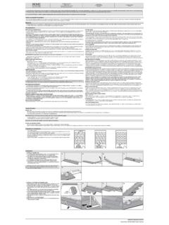
1 Installation Instructions BEFORE YOU BEGINRead these Instructions completely and carefully. IMPORTANT Save these Instructions for local inspector s use. IMPORTANT Observe all governing codes and ordinances. Note to Installer Be sure to leave these Instructions with the Consumer. Note to Consumer Keep these Instructions for future reference. Product failure due to improper Installation is not covered under the This appliance must be properly grounded. ATTENTION INSTALLER ALL COOKTOPS MUST BE HARD WIRED (DIRECT WIRED) INTO AN APPROVED JUNCTION BOX. A PLUG AND RECEPTACLE IS NOT PERMITTED ON THESE PRODUCTS. Proper Installation is the responsibility of the installer and product failure due to improper Installation is NOT covered under INCLUDEDMATERIALS YOU WILL NEEDTOOLS YOU MAY NEED30 and 36 Electric Cooktop - InductionCUTTING THE COUNTERTOPIf you are installing the Cooktop in a solid surface material such as granite, quartz or any other natural or synthetic solid surface, we recommend that the cutout be prepared by a professional cabinet or countertop cutouts in wood or wood-laminate countertops may be able to be prepared using a saber saw and Electric Rev.
2 2 11-18 GEAB affle(For all installationsexcept over an oven)2 Hex-Head ScrewsFoam TapeWB06K50422 Hold Down Brackets or order alternate Installation kit WB01X245704 Phillips ScrewsWB01X1137 Saber SawPencilSafety Glasses1/8" Drill Bit & Electric or Hand DrillRuler or StraightedgePhillips Head Screwdriver1/4" Nut Driver Large Size Wire NutsJunction Box (Sized for conduit per local electrical codes.)90 or Straight Squeeze Connector for 1 ConduitQuestions? Call us at or visit In Canada, call or visit Rev. 2 Installation InstructionsIMPORTANT SAFETY INSTRUCTIONSFOR YOUR SAFETY For Personal Safety, remove house fuse or open circuit breaker before beginning Installation . Failure to do so could result in serious injury or death. Be sure your Cooktop is installed properly by a qualified installer or service technician. To eliminate the risk of burns or fire due to reaching over heated surface elements, cabinet storage located above the surface units should be avoided.
3 If cabinet storage space is to be provided, the risk can be reduced by installing a range hood that projects horizontally a minimum of 5 beyond the bottom of the cabinets. Cabinet Installation above the Cooktop may be no deeper than 13 . Make sure the cabinets and wall coverings around the Cooktop can withstand the temperatures (up to 200 F) generated by the Cooktop . The Cooktop should be easy to reach and lighted with natural light during the day. Always disconnect the electrical service to the Cooktop before repairing or servicing the Cooktop . This can be done by disconnecting the fuse or circuit breaker. Failure to do this could result in a dangerous or fatal shock. Know where your main disconnect switch is located. If you do not know, have your electrician show REQUIREMENTSThis appliance must be supplied with the proper voltage and frequency, and connected to an individual, properly grounded branch circuit, protected by a circuit breaker or a time delay fuse as noted on name plate and on the chart the chart below to determine the minimum recommended dedicated circuit protection:KW Rating240 VKW Rating208 VRecommendedCircuit Size(Dedicated).
4 : .:20 KW KW KW30 KW KW KW40 KW KW KW KW50 AmpWe recommend you have the electrical wiring and hookup of your Cooktop connected by a qualified electrician. After Installation , have the electrician show you where your main Cooktop disconnect is must conform to National Electrical Code and all local electrical codes. You can get a copy of the National Electrical Code, ANSI/NFPA No. 70-Latest Edition, by writing to:National Fire Protection AssociationBatterymarch ParkQuincy, MA 02269In Canada, wiring must conform to Canadian Electrical Code (CEC).The Cooktop conduit wiring is approved for copper wire connection only, and if you have aluminum house wiring, you must use special UL approved connectors for joining copper to aluminum. In Canada, you must use special CSA approved connectors for joining copper to must use a two-wire, three conductor 208/240 VAC, 60 Hertz electrical system. A white (neutral) wire is not needed for this unit.
5 The Cooktop must be installed in a circuit that does not exceed 125 VAC nominal to to the name plate on your Cooktop for the KW rating for your Cooktop . These cooktops require 40 amp service for 30 units, 50 amp service for 36 plate location31-2000021 Rev. 23 Installation InstructionsPRE- Installation CHECKLISTBEFORE YOU BEGINWARNING The electrical power to the Cooktop supply line must be shut off while connections are being made. Failure to do so could result in serious injury or When preparing the Cooktop opening, make sure the inside of the cabinet and the Cooktop do not interfere with each other. (See section on preparing the opening.)B Remove packaging materials and literature package from the Cooktop before beginning Be sure to place all literature, Owner s Manual, Installations Instructions , etc. in a safe place for future Make sure you have all the tools and materials you need before starting the Installation of the Your home must provide the adequate electrical service needed to safely and properly use your Cooktop .
6 (Refer to section on electrical requirements.)F When installing your Cooktop in your home, make sure all local codes and ordinances are followed exactly as Make sure the wall coverings, countertop and cabinets around the Cooktop can withstand heat (up to 200 F) generated by the Installing Cooktop in combination with other products. Both products must be installed according to their specific product Installation Instructions . Consideration must be given to the separate electrical requirements and locations: Over one or two wall ovens: Only certain models may be installed over wall ovens. The wall oven and Cooktop will both have a label stating which models are approved in combination. Over a Microwave: See microwave Installation Instructions for how to install a microwave under a Cooktop . For vertical dimension of Cooktop , see Approximate Cooktop Dimensions section. In combination with telescopic downdraft vent: See telescopic downdraft vent Instructions for how to install a vent behind a Cooktop .
7 The countertop must have a deep flat surface to accommodate the combined Installation of the Cooktop and vent. Allow 12 clearance between the inlet air ports on the bottom of the unit. Over a warming drawer: See warming drawer Instructions for how to install a warming drawer under a Cooktop . For vertical dimension of Cooktop , see Approximate Cooktop Dimensions Monogram Flush Mount Kit If you intend to mount your Cooktop flush to the counter, please order kit number JXFLUSH1. The flush mount kit provides supplemental cut-out Instructions to mount the product flush with the Rev. 2 Installation InstructionsPREPARING THE OPENING1 APPROXIMATE Cooktop DIMENSIONS3 The following MINIMUM clearance dimensions must be a 30 clearance between the cooking surface and overhead combustible materials or metal cabinets cannot be maintained, a minimum clearance of 24 is required and the underside of the cabinets above the Cooktop must be protected with not less than 1/4 insulating millboard covered with sheet metal not less than 30 gage ( ) thick.
8 A ventilation hood may be installed above the Cooktop . See the ventilation hood Installation Instructions for the appropriate dimensions and Make sure the wall coverings, countertop and cabinets around the Cooktop can withstand heat (up to 200 F) generated by the CUTOUT DIMENSIONS OF THE COUNTERTOPTo ensure accuracy, it is best to make a template when cutting the opening in the ModelsXYZ Front Z Rear*30 PHP9030 DJBB CHP9530 SJSS ZHU30 RSJSS29 3/4 21 4 5/8 3 1/4 30 PHP9030 SJSS 29 7/8 21 4 5/8 3 1/4 36 PHP9036 DJBB CHP9536 SJSS ZHU36 RSJSS36 20 1/2 4 5/8 3 1/4 36 PHP9036 SJSS 36 1/8 20 1/2 4 5/8 3 1/4 * Depth at rear of Cooktop at conduit location. CooktopX30 models: 19 1/4 36 models: 18 7/8 ZY30 models: 28 1/16 36 models: 33 3/4 Use a cabinet base equal to or larger than the nominal width of the Cooktop (30 or 36 ).28 1/2 (30 )33 7/8 (36 )length of cut1-3/4 MIN.
9 Between rear edge of cutout and the wall behind the 5/8 (30 )19 1/8 (36 ) width of cut2-1/2 MIN. From front edge of cutout and front edge of " MAX. Depth of unprotected overhead cabinets2" MIN. Clearance from cutout to side wall on the left of the unit15" MIN. Height from countertop to underside of nearest cabinets on both sides of Cooktop , including any light rails2" MIN. Clearance from cutout to nearest vertical wall or cabinet on right side of the unit below the 15 MIN. clearance heightSee label next to name plate for minimum clearance to rear " MIN. Clearance from countertop to unprotected overhead surfaceWall coverings, cabinets and countertop must withstand heat up to 200 F. Baffle dimensionsBaffleFront5 5 3/16 31-2000021 Rev. 25 Installation InstructionsPREPARING THE OPENING (Cont)INSTALLING THE COOKTOP5 VERTICAL CLEARANCESA llow 3 minimum vertical clearance for air space from the Cooktop bottom (or 5-7/8 minimum depth from the countertop) to any combustible surfaces, such as the top of a cabinet INSTALLING THE JUNCTION BOXI nstall an approved junction box where it will be easily reached through the front of the cabinet where the Cooktop will be located.
10 The Cooktop conduit is 4 feet long. WARNING The junction box must be located where it will allow considerable slack in the conduit for PROTECT SURFACE OF COOKTOPP lace a towel or tablecloth onto the countertop. Lay the Cooktop upside down onto the protected INSTALL BAFFLES ecure the baffle to the Cooktop with : Do not install the baffle when the Cooktop is installed over a single FOR AMERICANS WITH DISABILITIES ACT (ADA) FORWARD APPROACH Installation ONLYA llow 5 minimum depth between the countertop and an : The enclosure must be made of at least 1/4 wood material. Also, an access panel is required for the junction box, hold-down brackets, and junction box so that it can be reached through the front of the of CooktopCloth under CooktopHex Head ScrewsRear of CooktopDRAWER3" 5-7/8" 5"631-2000021 Rev. 2 Installation InstructionsINSTALLING THE Cooktop (Cont)4 ATTACH FOAM TAPEA pply the foam tape around the outer edge of the glass.